Reflection
The found objects assignment was a good example of how important clear and congruent explanations are required for technical writing. I feel that several class mates had used too many broad words to describe positioning of items and or pieces. Several times while building other classmates’ objects the words chosen to describe placement could have represented several places on their items.
I tried my best to properly describe the pieces in the instructions with color and size. I had even measures in inches in my table of items to help the user. I needed to take into consideration to how many different ways could someone interpret a step. Several times I had even used a thesaurus to be sure. I was happy to see that my classmates were able to build my design using my directions.
Procedures
Parts List
|
|
3 |
Red Elbow |
3 |
|
Red Bar (5.0”) |
1 |
Orange Connector |
20 |
|
Blue Bar (2.0”) |
6 |
White Circular Connector |
6 |
|
|
|
Tan Node |
1 |
**Due to lack of rubber bands and the habit of them
breaking, the rubber band will be already assembled. Please so not pull back
hard on the rubber band.
**The ammo will be supplied by me upon request.
The Bolt:
1)
Take the
remaining red elbow (That has a rubber band connected to it.)
2)
Connect the
middle socket of the red elbow to the end of the red bar.
The Shaft:
1)
Along the length
of a grey bar place two red elbows using their middle socket.
2)
Slide the red
elbows all the way to the left side. (Their holes should line up.)
3)
Next attach a
white circular connector along the same grey bar as you did in the last step.
4)
Slide the white
circular connector to the left.
5)
Place four orange
connectors onto the same grey bar in the same fashion.
6)
Slide the four
orange connectors to the left.
7)
Repeat steps 3
through 7 over until the grey bar is full.
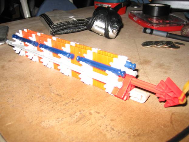
8)
The Object at
this point should look as the following. Two reds, one white, four oranges, one
white, four oranges, one white, four oranges, one white, four oranges, one
white, for oranges, ending with one white.
9)
Each of the parts
should line up to each other by their holes.
10)
Attach the tan node to the end of the grey bar that of the shaft that comes out
of the two red elbows. Turn the tan node so that it is facing downward.
The bottom of the object is
the side along the grey bar which connects the entire shaft.
Reinforcement:
1)
Along the length
of the left side connect a grey bar to the shaft so that it connects to each of
the six white circular connectors. (Push any excess material to the right.)
2)
Along the length
of the right side connect a grey bar to the shaft so that it connects to each
of the six white circular connectors. (Push excess material to the right.)
3)
There should be
one open socket on each white circular connector between the left grey bar and
the very top, and one between the right grey bar and the very top. (The very
top space should have nothing connected to it.)
4)
Using these open
spaces connect two blue bars to the first and second white circular connectors.
5)
Using these open
spaces connect two blue bars to the third and fourth white circular connectors.
6)
Using these open
spaces connect two blue bars to the fifth and sixth white circular connectors.
Assembly:
1)
Slide the bolt
down into the circles of the shaft on the left side. (The side with the two red
elbows.)
2)
Slip the rubber
band on to the tan node.
Directions:
1)
Load a metal bb
down the shaft.
2)
Pull back on the
bolt and release.
Don’t pull the bolt too far or it
will come out.
The Object