Go to ECE 291 Experiment  1   |   2    |  3   |   4   |  5   |  6   |  8   |  9   |   10   |   11   |    ECE Lab home

ECE291 - LABORATORY VII

INPUT IMPEDANCE OF AN OSCILLOSCOPE AND THE SCOPE PROBE


OBJECTIVES

Measurement of the oscilloscope input impedance. Principles of operation and usage of the scope probe.


INTRODUCTION

After becoming familiar with the frequency response of RC circuits in the previous laboratory, you are ready to learn about the oscilloscope input impedance. This complex impedance, which has resistive and capacitive components, can disturb performance of circuits being measured and limits high frequency performance of oscilloscopes. Fortunately there is a remedy, which you should know about: the scope probe.

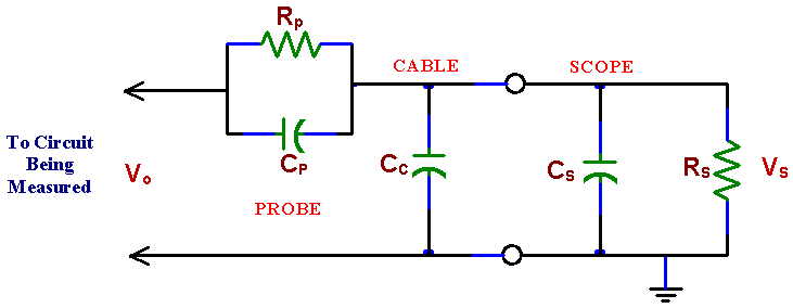
A scope probe is essentially a 10:1 attenuator with a resistor and a capacitor at the end of the probe cable. The attenuator consists of two impedances in series, one of which is the scope’s own impedance to ground while the other is attached between the point of measurement in a circuit and the scope input. For only dc measurements we could use a resistor as the external impedance. The same would be true also for ac measurements if the scope internal impedance was only resistive. The scope internal impedance, however, has a capacitive component. Note that the capacitance of the scope cable adds to the internal capacitance of the scope input. This not only makes it much larger but also dependent on the length of the cable used. Very bad for high frequency measurements! To make things worse, the load that the scope with its cable presents to a measured circuit depends on frequency and amplitude measurements with the scope are frequency dependent. The scope probe solves this problem not by eliminating this capacitance (which is not possible) but by compensating it with another capacitance. The probe capacitance is chosen so that the measurement is independent of frequency.

If the probe impedance is not matched properly to the scope internal impedance the attenuation depends on frequency and thus acts as a filter. Fortunately there is an easy way to adjust the probe impedance with a built-in small trimming capacitor. A filter distorts a square wave so the trimming capacitor can be adjusted by observing a distortion of a square wave on the scope screen. Oscilloscopes are equipped with internal square wave generators for easy probe adjustments. The probe test terminal is provided on the front panel. The probe capacitor is adjusted until there is no distortion of the square wave.

A scope probe is a very handy device used by professionals all the time. From now on you should use it too!

Fig. 5. The circuit representing an oscilloscope with a probe.

RS -scope internal resistance, CS scope internal capacitance, CC - cable capacitance, RP - probe resistance, CP - probe capacitance


Measuring the impedance of an oscilloscope

Measuring the scope internal resistance (RS) is easy; just like a voltmeter resistance, using a DC source. For measurements of the scope internal capacitance AC source must be used, of course. An external resistor R is put in series with the voltage source (instead of the probe in Fig. 5).

From the voltage divider formula:

where Z1 is the scope impedance (including the cable capacitance CC), so that Z1 = RS ||CS || CC   or


where C = Cs + Cc. Z2 is just the external resistance R, Z2 = R

Measuring amplitudes Vo, Vs of Vo and Vs gives us:

where red letters denote complex variables while a and b are the real and the imaginary parts of the impedance ratio in the last equation.

PRELAB

If the scope internal resistance is RS, its capacitance is CS, and the cable connecting the probe to the scope has capacitance CC, find the values of the required probe resistance RP and capacitance CP for 10:1 attenuation. Make sure that the same attenuation is also valid for dc measurements.

Hint: Consider independently two voltage dividers, one resistive the other capacitive. Note that they are connected in parallel and should give the same attenuation.

References: T. C. Hayes and P. Horowitz "Student Manual for The Art of Electronics" pp. 62-632. Cambridge University Press 1989. Also in P. Horowitz and W. Hill "The Art of Electronics" 2-nd edition.


LABORATORY

Equipment needed from the stockroom: scope probe, resistance substitution box, parts kit, proto-board, leads.

1.    MEASUREMENT OF THE INTERNAL IMPEDANCE OF AN

OSCILLOSCOPE.

The input impedance of an oscilloscope is a complex quantity which can be represented by a resistance in parallel with a capacitance between the scope input terminal and the ground. The impedance is thus frequency dependent.

a)     First, determine the internal scope resistance with a DC signal. Apply the same method as used for the measurement of a voltmeter internal resistance. You may use a resistance substitution box for this measurement. Select resistance which causes the voltage to drop to about 1/2 of the voltage measured directly (without the resistance). Use the oscilloscope for the two dc measurements (with and without the resistor).

b)    Repeat the measurement but instead of DC use a sinewave signal with a frequency at which the scope impedance is significantly different from the measurement a). Since the AC scope impedance is lower than its DC impedance (because of the parallel capacitance), use a resistor of a smaller value than in a). Moreover, the voltage measured by the scope depends now also on frequency, because the ratio of the voltage divider formed by the external resistor and the scope impedance depends on frequency. A resistor of a few tens of kilo ohms and a frequency of a few tens of kilo hertz is a good choice. Do not use resistance substitution box in this case as its capacitance may influence the measurement.

c)    Using a capacitance meter available in the laboratory, measure the capacitance of the coaxial cable connected to the scope during these measurements. The cable capacitance contributes to the scope capacitance seen by the circuit. Determine also the cable length and calculate its capacitance per unit length.


2.   SCOPE PROBE.

2.1.    Check your scope probe by connecting it to the probe calibration terminal on your scope. Properly adjusted probe should give the same attenuation for all frequencies, which means that it passes a square wave signal without distortion. If you do not see a perfect square wave, using a small screwdriver adjust the probe trimming capacitor which tunes Cp.

2.2.   To see the benefits of using the probe make a 2:1 resistive voltage divider, using equal resistors of 50 k to 100k. Particular resistance values are not critical, as long as you know their ratio; check it with the digital ohmmeter. Measure attenuation of a sinewave at two frequencies, in 10 kHz and 100 kHz range using (a) scope without the probe (b) scope with probe.

3.   CIRCUIT SIMULATION (at home).

Simulate the circuit representing an oscilloscope probe (Fig. 5). Use the values of RS, CS, and CS, from your measurements and the corresponding values of RP and Cp for 1:10 attenuation.

a)     Simulate the effect of tuning of CP (by slightly increasing and decreasing it from the "ideal" value) on the shape of a square wave at the probe input. Compare also frequency responses of a tuned and an out of tune probe.

b)    Simulate the measurements 2.2 with and without the probe.


REPORT

  • Calculate RS from dc the measurement in 1. With the known value of Rs and the ac measurements in 1, calculate Cs (see the introduction to this laboratory). Do not forget to subtract the cable capacitance. RS and CS determine the input impedance of the scope.


  • Explain the result of measurements in 2.2.


  • The fact that the scope probe attenuates the signal does not appear to be an advantage. Why then is the probe so useful in scope measurements?

  Go to ECE 291 Experiment  1   |   2    |  3   |   4   |  5   |  6   |  8   |  9   |   10   |   11   |    ECE Lab home