Go to ECE392 Experiment | 1 | 3 | 4 | 5 | 6 | 7 | 8 | Lab manuals | ECE Lab home
![]()
|
|
Go to ECE392 Experiment | 1 | 3 | 4 | 5 | 6 | 7 | 8 | Lab manuals | ECE Lab home |
|
ECE 392 - Electrical Engineering Laboratory II
EXPERIMENT II
THE EMITTER FOLLOWER
PRELAB
What is the
approximate value of the voltage gain of an emitter follower? Why may such a
circuit be useful?
What are the values of input and output impedances of the emitter follower you expect to measure? Are they related?
LABORATORY
1. EMITTER FOLLOWER WITH SINGLE AND DOUBLE POLARITY POWER SUPPLIES.
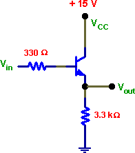
Wire the circuit shown below. The value of the small protective input base resistor is not critical.

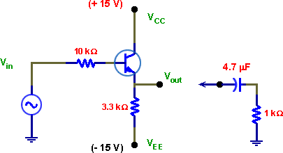
mF blocking capacitor. Use a sinusoidal signal at the input and observe a change in the output signal when the resistor is connected. Determine the Thevenin equivalent resistance viewing the follower as a voltage source with Zout in series. Work at a frequency at which the load circuit does not act as a filter.
Drive it with a symmetrical sine wave at the input (check that the signal from the waveform generator has no dc offset voltage). Increase the input voltage from less than 1 V (p-p) to about 5V (do not drive the B-E junction to breakdown on a negative half cycle). Observe input and output waveforms on a scope and note their amplitudes and phase relation. Use the scope DC input to see if there is a dc bias on your signal.
Next connect VEE to -15 V (see the figure below) and observe the output again. Measure input and output voltages. Calculate voltage gain.
How large output voltage can you get from the circuit (without distortion)?
Explain the difference between this and the previous case.
Measure the input and output impedances, Zin and Zout.
Determine Zin (the impedance looking into the transistor base) by measuring signals on both sides of the 10k resistor connected in series at the input. You may leave in place the small input resistor used in the previous circuit.
Load the output with a resistor (1k or less) through a 4.7
Hint: Note that the load resistor forms a voltage divider with Zout.

2. EMITTER FOLLOWER WITH COUPLING CAPACITORS.
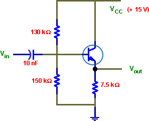
Can you use a single polarity power supply for a follower operating with a symmetrical input? Try the circuit shown in the figure below. Measure both ac and dc components of the output voltage with a scope. Measure the emitter and base dc bias with a DVM.
Explain results. How could you eliminate dc component from the output voltage? Try!

1? Determine frequency f-3dB.Do you think that the frequency response of the last circuit is different than those in
REPORT
Present clearly the result of all measurements. Answer all questions and comment on topics typed in bold print in this manual.
Use PSPICE simulation to obtain the frequency responses of the circuit in 2.
|
|
Go to ECE392 Experiment | 1 | 3 | 4 | 5 | 6 | 7 | 8 | Lab manuals | ECE Lab home |
|