|
|
Note: in this manual, square brackets "[" and "]" indicate that the parameters enclosed within are optional. Please do not include square parameters in parameter lists (their use is reserved for array indices).
Δ Physical Units
The following units are implied for numerical constants:- Length: [L] = µm
- Time: [T] = ms
- Concentration: [c] = µM
- Current: [ICa] = Q [c] [L]3 / [t] = Q 10-21 moles / ms = 602.214 Ca2+ ions per ms
whereQ = 2 eis the charge of a Ca2+ ion.
Current can also be specified in pA using the built-in constant pA = 5.182134 [ICa] = 3120.75 Ca2+ ions per ms.
Important note: when you plot the value of Ca2+ current (say, using the built-in variable _ICa or otherwise), it will always be given in these internal units, not in units of pA, so remember to divide by 5.182134 to obtain values in pA.
Units for other quantities are derived from the above; for example, units for the diffusion coefficient are [L]2/[T] = µm2/ms
Of course, one is free to use a different choice of units; in that case one should ignore the unit symbols prompted by the program in various text messages.
Δ General syntax
- Definition language is Case-Sensitive.
- Comment character is "%": % this is a comment
- Semicolon (";") separates statements that follow one another on the same line:
grid 20 20 20 ; stretch.factor = 1.07
- To continue a definition on another line, put a line continuation string "..."
at the end of the previous line:
Ca.bc Noflux Noflux Noflux Noflux ...

                Pump Pump
- A parameter name can be used wherever a numerical value is expected:
grid N N N ; N = 40
- A constant numerical expression may be used for defining any
parameter, i.e.
grid N M M ; N = 2 * M ; M = 10
- If a parameter or construct is defined multiple times within the script,
only the first definition will be used.
- Parameter definitions may appear in arbitrary order throughout the
script, unless the conditional if .. then .. else .. endif
statement is used,
in which case the order of appearance of definitions is arbitrary within each of the
then .. else/endif and else .. endif blocks.
The only exception are Run and current statements which
specify the simulation runs themselves and are executed in the order of their appearance.
- Non-trivial program flow can only be arranged via combined use of the for loop
statement, the conditional "if" .. "then" .. "else" .. "endif"
statement, the "include" statement and the
"print/append" statements (see the description of the
"if" statement).
- Parameter/identifier names can include all kinds of special characters, if the names are enclosed in
quotes:
"Ca\s0\N\S2+\N" = 0.1(this creates an xmgr-friendly name with a subscript and a superscript).
Δ Mathematical expression syntax
- A space between two numerical values implies multiplication:
x = 20 exp( y ) is equivalent to x = 20 * exp( y )
- The following functions can be used in numerical expressions:
sinh, cosh, tanh, sin, cos, tan, atan, exp, log, log10, sqr, sqrt, theta, sigma (sigma(x) = ( 1 + tanh(x) )/2 ), int (integer part of float), not (logical negation), rand(0) (random number between 0 and 1)
- Time variable is "t"
(to be used only in time-dependent variable definitions - see below).
- Operator execution priorities:
Operators are executed in the same order as in the C programming language. Below all operators are listed according to their execution order, from highest to lowest:
Unary boolean not operator:
Binary exponentiation operator:!
Unary sign operator:^
Binary arithmetic operators:- * / mod
Binary logical operators:+ - < <= > >= == (equal) != (not equal) and or
-
Boolean operations: logical operations evaluate to 1 if true, and to 0 if false.
An argument of a logical operator is considered true if greater than zero, and false otherwise.
Logical operators include the binary operators from the table above, and the not( ) function.
The primary use of logical expressions is in the "if" conditional statement, but they may also
be used in other expressions:
F := 2 * (t > 1.0) + (t <= 1.0)
- defines a function of time equal to 1.0 when simulation time is less than 1.0 ms, and equal to 2.0 otherwise.
-
Constant arrays may be defined, using a space-separated list:
Data = 1.2 0.9 0.8 1.1 1.3 1.5 % defines the array
The curly-bracket references can also be used to extract arguments of a compound definition, such as the grid definition. Example:
entry = Data{4} % getting the 4th element (Data{4} = 1.1)grid 20 40 30
To obtain the number of elements in the array, use array{0}. For instance, in the above examples grid{0} returns 3, and Data{0} returns 6.
gridString = "The grid size is " grid{1} " by " grid{2} " by " grid{3} " points"
Δ String expressions
A string is a sequence of characters in quotes, either"..." or '...';
the closing quote must be the same as the opening quote:
string_variable = "@#$%^!"
To include quote characters in a string, mix-and-match quote types:doubleQuote = '"' Any string label/name (for instance, a file name) can be defined as a concatenation of several substrings:
string = token1 token2 ...
where token1, token2, ... are either strings or numerical expressions. The latter will be evaluated and their values converted to strings. Example:
param = 4
fileName = "var." 2 * param
plot mute var fileName
The time dependence of a user-defined variable "var" will be saved in file "var.8".
This feature is particularly useful when running a for loop over a parameter value.There is a side-effect of this free-form mixing of string and numerical expressions: if a string expression matches a variable name, it will be interpreted as a variable. In the above example, string defined as
fileName = "var." "param" is equal to var.4, not var.param.
Δ The include statement
A script file can import another script file using command include file_name. The scriptfile_name will be inserted at the point where the include command appears.
One may also use a string variable as a file name, if it is defined
earlier in the file, i.e.:script = path "/script"
include script
Δ Command-line parameters
Command-line arguments passed to CalC are accessible within the script; the n-th argument is denoted $n (note that the 1st argument is the script file name itself). The total number of arguments appearing on the command line is stored into a constant named $$Δ Implemented Geometries
Although the description of various definition commands that follow below assume a 3D model in cartesian coordinates (the default geometry), various lower-dimensional geometries have also been implemented. To specify the model geometry, use the commandgeometry = geometry_name
where thegeometry_name is a geometry label that assumes one of
the string values listed in the table below:
Dimensionality | Geometry label |
Axis labels | Geometry description |
1D |
cartesian.1D | x | 1D model: diffusion along a line |
| disc | r | Diffusion inside a disc: rotationally symmetric geometry | |
| spherical | r | Fully spherically symmetric geometry | |
2D |
cartesian.2D | x y | 2D model in cartesian coordinates |
| cylindrical | r z | 2D model in cylindrical coordinates | |
| polar | r phi | 2D model in polar coordinates | |
| conical | r theta | Model in spherical coordinates, symmetric with respect to phi azimuth angle | |
3D |
cartesian.3D << default >> | x y z | Full 3D model in cartesian coordinates |
| spherical.3D | r theta phi | Full 3D model in spherical coordinates | |
| cylindrical.3D | r phi z | Full 3D model in cylindrical coordinates |
When using any of the lower-dimensionality geometries listed above, the argument lists of many of the definition instructions described below should be shortened. Additionally, some commands (e.g., plot and axis stretch instructions) use axis labels as arguments, which assume different string values depending on the geometry, as listed in the above table. Below is an example comparing some of the statements for the full 3D geometry in cartesian coordinates (geometry = cartesian.3D), and the reduced rotationally-symmetric geometry in conical and spherical coordinates:
| geometry = cartesian.3D | geometry = conical | geometry = spherical |
volume 0 1 0 1 0 1 |
volume 0 1 0 1.57 |
volume 0 1 |
grid 30 30 30 |
grid 30 30 |
grid 30 |
stretch x 0 0.1 |
stretch r 0 0.1 |
stretch r 0 0.1 |
stretch y 0 0.1 |
stretch theta 0 0.1 |
|
stretch x 0 0.1 |
||
Ca.source 0 0 0 |
Ca.source 0 0 |
Ca.source 0 |
plot Ca[0.2,0,0] |
plot Ca[0.2,0] |
plot Ca[0.2] |
plot 1D Ca x 0 0 |
plot 1D Ca r 0 |
plot 1D Ca |
plot 2D Ca z 0.2 |
plot 2D Ca |
Few special geometry cases (spherical, cylindrical and conical) are described in more detail below, as an example.
Δ Spherically-symmetric geometry
When the geometry is spherically symmetric, the 3D problem reduces to a 1D problem in spherical coordinates. Examples are: a source in the center of a sphere, or a current uniformly distributed over the surface of a spherical cell. In this case it is much more efficient to solve the resulting one-dimensional problem. To do so, use the commandgeometry = spherical
and only use two parameters when defining the volume:volume R0 R1
whereR0 and R1 are the inner and outer radii of the spherical shell
that serves as the diffusion space in this case. Only two boundary
conditions need to be defined, one for the inner and one for the outer surfaces of
the shell.Similarly, only two parameters specify the Ca current source:
Ca.source R dR
where"R" specifies the radius of the spherical surface over which the current
is uniformly distributed (R=0 for a problem with a source in the center of a sphere),
and "dR" specifies the width of the source current layer in radial direction.All other commands also remain unchanged; wherever an axis name is needed, use
"r",
and omit the "y", "z" coordinates. For example,
use stretch r rmin rmax to stretch
the grid outside of the shell [rmin, rmax], use Ca[r] to access
calcium concentration at distance r from the center,
and plot 1D Ca to plot the calcium concentration as a function of
distance from the center of the sphere.
Δ Cylindrical geometry
If the geometry of the problem is symmetric with respect to the azimuth anglephi in
cylindrical coordinates, the 3D problem reduces to a 2D problem in
coordinates r and z.
To solve the corresponding 2D problem, include the command
geometry = cylindrical
and only use four parameters when defining the volume:volume R0 R1 Z0 Z1
whereR0 and R1 are the inner and outer radii of the volume, and
Z0 and Z1 are the limiting z-values.
Only four boundary
conditions need to be defined.
Similarly, only four parameters specify the Ca current source:
Ca.source R Z [ dR dZ ]
whereR, Theta specify the location of the source, and optional
parameters dR, dZ specify the spread of the source.All other commands are also analogous to their 3D counterparts. Wherever an axis name is needed, use
"r"
for the radial coordinate, "z" for the 2nd coordinate.
and omit the "z" coordinate. For example,
use stretch z zmin zmax to stretch
the grid outside of the domain [zmin, zmax], use
Ca[r,z] to access
calcium concentration at location {r, z}, use
plot 1D Ca z r0 to plot the calcium concentration as a function of
z, at a distance r0 from the center of the sphere.
Δ Conical geometry
If the geometry of the problem is symmetric with respect to the azimuth anglephi
in spherical coordinates, the 3D problem reduces to a 2D problem in
coordinates r and theta (e.g., see Klingauf and Neher (1997) Biophys J 72: 674).
To solve the corresponding 2D problem, include the command
geometry = conical
and only use four parameters when defining the volume:volume R0 R1 Theta0 Theta1
whereR0 and R1 are the inner and outer radii of the volume, and
Theta0 and Theta1 are the limiting angle values, in radian (0 < Theta0, Theta1 < pi).
For Theta0=0, the volume is a cone. Only four boundary conditions need to be defined. Similarly, only four parameters specify the Ca current source:
Ca.source R Theta [ dR dTheta ]
whereR, Theta specify the location of the source, and optional parameters
dR, dTheta specify the spread of the source.All other commands are also analogous to their 3D counterparts. Wherever an axis name is needed, use
"r"
for the radial coordinate, "theta" for the angle coordinate,
and omit the "z" coordinate. For example,
use stretch theta thetamin thetamax to stretch
the grid outside of the angle domain [thetamin, thetamax], use
Ca[r,theta] to access
calcium concentration at location {r, theta}, use
plot 1D Ca theta r0 to plot the calcium concentration as a function of
angle, at a distance r0 from the center of the sphere.
Δ Geometry definitions:
Δ Rectangular / box enclosures and obstacles:
The simulation space volume can be composed of (is a union of) an arbitrary number of "boxes", spheres, cylnders, etc., each defined via keyword "volume", with an arbitrary number of obstacles (barriers to diffusion of calcium and buffers), each defined using keyword "obstacle". Definition syntax for a box volume reads:volume xmin xmax ymin ymax zmin zmax
- defines a box spanning area {xmin < x < xmax, ymin < y < ymax, zmin < z < zmax}. In any 2D geoemtry, only 4 arguments should be specified; only 2 arguments are needed in 1D geoemtry. Bounding coordinate are assumed to be in micrometers. If the diffusion space is composed of several boxes, several volume definitions should be included.obstacle xmin xmax ymin ymax zmin zmax
- defines a diffusion obstacle spanning an area {xmin < x < xmax, ymin < y < ymax, zmin < z < zmax}An arbitrary number of obstacle definitions may be used.
Δ Spheres, cylinders and disks in Cartesian coordinates:
In CalC versions 6.7 and above and 7.7 and above, in the Cartesian 2D or 3D geometry the diffusion volume can be defined as a superposition of spherical, cylindrical or disk enclosures, defined using the same volume command explained above. The type of enclosure is determined by the number of arguments (in coding lingo, thevolume / obstacle commands are overloaded)
volume xCenter yCenter zCenter radius % In cartesian.3D, it's a sphere: note 4 arguments
volume xBase yBase zBase zTop radius % In cartesian.3D, it's a cylinder: note 5 arguments
volume xCenter yCenter radius % In cartesian.2D, it's a disk: note 3 arguments
Analogously, one can define spherical dffusion obstacles (e.g. vesicles):obstacle xCenter yCenter zCenter radius % It's a spherical obstacle: note 4 arguments
obstacle xBase yBase zBase zTop radius % It's a cylindrical obstacle: note 5 arguments
obstacle xCenter yCenter radius % It's a disk obstacle: note 3 arguments
See a simple example here. Note that keywords sphere and sobstacle are now obsolete but still work.Δ Defining volumes and obstacles by a formula:
NEW: starting with versions 6.8.0 / 7.8.0, it is possible to define an arbitrary diffusion volume using a piece-wise smooth function of the relevant geometry variables. Points for which the function evaluates to a positive value are assumed to be inside. The first 6 parameters (or 4 parameters in a 2D geometry) must include the bounding box of this volume. The general expression in the defaultCartesian.3D geometry is:
volume xmin xmax ymin ymax zmin zmax = [ function of x, y, z ]
For example, the following definition is equivalent to the sphere definition volume 2 2 2 2 :volume 0 4 0 4 0 4 = (x - 2)^2 + (y - 2)^2 + (z - 2)^2 < 4
For obstacles, the bounding box parameters should be omitted; the following defines a box volume with a vesicle obstacle:volume 0 4 0 4 0 4
obstacle = (x-2)^2 + (y-2)^2 + (z-1)^2 < 1
Mixing of boolean and algebraic operations is allowed (see description of boolean operations), in the usual C-language convention; for instance, the following defines a half-sphere:volume 0 4 0 4 0 2 = ( (x - 2)^2 + (y - 2)^2 + (z - 2)^2 < 4 ) * (z < 2)
Another example: the following expression defines a cylinder parallel to the x-axis, with length 5 and radius 1:volume 0 5 -1 1 -1 1 = ( y^2 + z^2 < 1 ) * (x > 0) * (x < 5)
Note: curvilinear volumes/obstacles are still under testing: curved boundaries may reduce stability of finite-difference scheme. If you see ringing (high-frequency modes) in your output data, reduce the tolerance value for adaptive time-stepping, e.g. adaptive.accuracy = 1e-6. Future versions of CalC will continue improving the handling of curved boundaries.
Δ "Special" single-field obstacles:
To define areas that are impermeable to a particular buffer molecule, one can also define special buffer obstacles. This is a simple alternative to defining non-uniform diffusivity through the tortuosity definition. The format for a special obstacle is very similar to the definition of a usual obstacle; one only needs to add the buffer name prefix:buffer_name.obstacle xmin xmax ymin ymax zmin zmax
Δ Grid specification:
Calcium and buffer concentration fields are computed on a mesh of points, specified using keyword "grid", covering the entire diffusion space. The grid may be non-uniform. CalC uses a simple cubic grid, which is a direct product of spatial grids along the individual axes. To define a grid of size nx by ny by nz, usegrid nx ny nz
The number of points in each direction should be an odd integer; an even number will be increased by 1.When using geometries with spatial dimensionality of 1 or 2, use respectively 1 or 2 integer arguments only, corresponding to the respective grid dimensions.
Δ Non-uniform grid:
For the same number of grid points, the accuracy of the computation can be improved by increasing the density of grid point in the vicinity of calcium channel(s), where the concentration gradients are the greatest. If the channel array is enclosed within a region {xmin < x < xmax, ymin < y < ymax, zmin < z < zmax}, one should use:stretch x xmin xmax
stretch y ymin ymax
stretch z zmin zmax
- each successive grid interval further away from the region
{xmin < x < xmax, ymin < y < ymax, zmin < z < zmax} will be multiplied by a factor
specified by stretch.factor, which should be slightly greater than 1.0:
The grid may also be stretched along a single direction (x, y, or z) only.
stretch.factor = value
- sets the grid non-uniformity factor used by stretch. Recommended values for the factor value are between 1.05 and 1.2. Using larger values, while making the results converge faster with increasing grid dimensions (i.e. spatial resolution), will cause the results to converge to a slightly wrong answer (stretching the grid introduces an additional systematic computation error).The
stretch command syntax is the same for spherical,
disc, cylindrical and conical geometries, except that
one may use, respectively, the direction labels "r", "r" and "z",
or "r" and "theta", i.e.
stretch r rMin rMax
stretch theta angleMin angleMax
Δ Calcium and buffer definitions:
Definition of each Ca2+ property starts with a labelCa followed by a period, then
followed by the property name:
Ca.bgr = expression
- defines the initial background calcium concentration (in units of µM)Ca.D = expression
- defines the value of the calcium diffusion coefficient (in units of µm2/ms)Buffer properties definitions have the same syntax. For example, definition of a diffusion coefficient of a buffer named
Bf is Bf.D = expression
In order to define a diffusion coefficient which is non-uniform in space, use the command
Ca.tortuosity = f(x,y,z)
The diffusion coefficient of Ca2+ will be a product of a space-independent term defined by Ca.D and the space-dependent term defined by a user-specified function f(x,y,z) Example:Ca.tortuosity = 1 - 0.5 exp( - 20 ( x*x + y*y + z*z ) )
- in this case the Ca2+ diffusion will be reduced in the vicinity of point x = y = z = 0.Diffusion coefficient of a buffer can be modified the same way, for instance:
buffer Fura
Fura.tortuosity = 1 - 0.5 sigma( 50 (z - 0.2) )
Fura.D = 0.118
............
To define the same tortuosity function for Ca2+ and all the buffers, simply usetortuosity = f(x,y,z) or all.tortuosity = f(x,y,z)
Note that the diffusion coefficient should have (approximately) zero derivative at the boundary in the direction normal to the boundary.Non-uniform diffusion coefficient is implemented for all cartesian and curvilinear geometries (1D, 2D and 3D).
Δ Boundary condition specification:
By default, both calcium and buffers satisfy zero flux (reflective) boundary conditions at all surfaces of all geometry elements. However, boundary conditions may be specified by the user for each volume and each obstacle (including special buffer obstacles), by providing the following statement for each geometry element:Ca.bc bcXmin bcXmax bcYmin bcYmax bcZmin bcZmax
This command specifies boundary conditions for each of the six surfaces of a volume element. Each of the labelsbcXmin ... bcZmax is either defined by the user via a
bc.define instruction described below, or is one of the two predefined types,
Noflux or Dirichlet (Bgr), corresponding respectively to
the zero flux (reflective) boundary condition, or to the boundary value clamped to background concentration.
In 2D geometry, only 4 boundary condition types should be specified, and only 2 are needed for 1D geometry.
If a concentration field satisfies the same boundary condition "bcName" at all
boundaries of a corresponding volume element, use
Ca.bc all bcName
If several volumes and/or obstacles are specified, the boundary condition definitions appearing earlier in the script will correspond to volume definitions (in the order those were defined), and the following boundary condition definitions will correspond to the obstacles, including any special buffer obstacles.Δ User-defined boundary condition:
The user definition of a boundary condition type allows one of the following four alternative forms:bc.define bcName A B C n K C2 n2 K2
bc.define bcName A B C n K
bc.define bcName A B
bc.define bcName R
wherebcName is a user-chosen label. In each of the above four alternative boundary condition definitions, parameters
A ... R correspond to the parameters in one of the corresponding four equations:

Here
[Ca] is the Ca2+ concentration at the boundary,
and [Ca]0 is the background concentration.
In the first two cases Flux is the flux per unit area at the boundary, with default units (in 3D) of
µM µm / ms = 10-6 mol / (m2 s) = 10-9 pmol / (µm2 ms),
and therefore the units of B are μm/ms = 10-3 m/sec. Units of
C and C2 are the same as units of flux. Default units of pump affinity
K and K2 are μM.
Non-linearity (cooperativity) power parameters n and n2
can be any real numbers greater than 1.
For instance, to simulate a linear saturable calcium pump on the bottom and top ("zmin" and "zmax") surfaces of a volume, with maximal pump rate of
0.01 µM µm / ms,
and dissociation rate of K = 0.2 µM, use the following command:
bc.define
Pump 1 0 0.01 1 0.2
Ca.bc
Noflux Noflux Noflux Noflux Pump Pump
The Noflux (zero flux) and Dirichlet / Bgr boundary condition types are defined internally using
bc.define Noflux 1 0
bc.define Dirichlet 0
bc.define Bgr 0
Note that if the calcium or a buffer field is to assume a fixed concentration value at the boundary which is not equal to its resting background
concentration, user has to provide his own redefinition for the Dirichlet boundary condition (using a different type
label/name, since the bc's already defined may not be redefined); for instance:
bc.define myDirichlet 0.1
Ca.bc all myDirichlet % the Ca concentration value is the background concentration plus
0.1 µM on all boundaries
Finally, note that buffers are assumed to satisfy either no-flux or Dirichlet boundary conditions only. If non-zero flux boundary conditions are desired for a buffer, two additional parameters are required, the background concentration and mobility of the buffer:
bc.define bcName A B C n K B_bgr DB
Δ Backward-compatible boundary condition definition:
For compatibility with versions of CalC preceding 7.6, the following alternative definition may be used:bc.define bcName A B C P
corresponding to boundary condition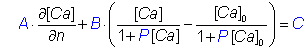
where
d[Ca]/dn is the derivative normal to the boundary facing out.
The value of P is zero by default. For the pump example above, with
maximal pump rate of Vm=0.01 µM µm / ms,
and dissociation rate of K = 0.2 µM, use
A = 1, B = −Vm / (K DCa) = -0.227 (µm-1),
where DCa=0.220 µm2/ms is the calcium diffusion coefficient,
and set P = 1 / K = 5 µM-1:
bc.define
Pump 1.0 -0.227 0.0 5.0
Ca.bc
Noflux Noflux Noflux Noflux Pump Pump
Δ Buffer definitions:
An arbitrary number of buffers with one-to-one Ca2+ binding stoichiometry can be included in the simulation, each defined usingbuffer buffer_name
Values specified for the calcium concentration field should also be specified for each of the buffers. However, instead of defining the background concentration, it is necessary to define itstotal concentration, using
buffer_name.total = constant_expression
For a mobile buffer, this total concentration is
assumed to be homogeneous throughout the diffusion space.
Example:
buffer myBuffer
myBuffer.D = 0.2
myBuffer.total = 2000
myBuffer.bc all Noflux
% (default setting)
Calcium binding kinetics should be specified for each of the buffers, by
defining two of the following three parameters:
myBuffer.kplus = expression
% defines calcium binding rate, in 1/(ms uM)
myBuffer.kminus = expression
% defines calcium unbinding rate, in 1/ms
myBuffer.KD = expression
% defines calcium affinity of buffer (in uM): KD = kminus/kplus
Before the simulation is initiated, the program automatically calculates the initial buffer concentration from its kinetic
parameters and total concentration value, assuming an equilibrium with the defined
background [Ca2+] (unless the
concentration field is initialized from a disk file using the import instruction).A fixed buffer can be localized to a given segment of the simulation volume, by using a spatially-dependent function in the
total concentration definition, for instance:
buffer myBuffer
myBuffer.D = 0 % buffer is fixed
myBuffer.total = 2000 * (x*x + y*y + z*z <= 0.01) % buffer is confined
to a spherical region around the origin, with a radius of 0.1 µM
For non-cartesian geometries, remember to use appropriate space variables (axis labels)
in the above expression for the total concentration (see table)
Further, one can define a fixed membrane-bound buffer, localized to a layer of a given
depth
over the entire boundary surface, using instruction
buffer buffer_name membrane [ depth ]
wheredepth is an optional numerical constant expression determining the thickness of the
buffer layer surrounding the boundary. If the
depth is zero (which is its default value if this parameter is omitted),
the buffer will be localized to one grid layer around the membrane, and the total
concentration should be specified in units of molecules per µm2. In order
to force molar concentration definition for a membrane-bound buffer instead, the following command
should be included anywhere within the script:
membrane.definition concentration
Membrane-bound buffer can be targeted to individual enclosurse and obstacles by listing integer parameters representing the order in which these enclosurse and obstacles were defined in the script. In this case the depth parameter is required. For instance, if the simulation domain consists of a single volume definition followed by two obstacle definitions, the following command targets the membrane buffer to the obstacles only:buffer buffer_name membrane 0.0 2 3
Δ Buffers with cooperative Ca2+ binding
To define a buffer with 1-to-2 calcium binding stoichiometry named"B", use keyword buffer cooperative:
buffer cooperative B
This will create three different concentration fields, with namesB, Ca.B and Ca2.B,
corresponding to the calcium binding states of the reaction
B + 2 Ca2+ ⇔ CaB + Ca2+ ⇔ Ca2B
The rates of the two reactions in the above diagram should be declared as properties of buffersCa and Ca.B,
respectively, even though the first unbinding is a property of Ca.B, not B: this simplifies
the syntax.
For example, the statements below define the properties of calmodulin's N-lobe as reported recently
by Faas et al. (2011):
buffer cooperative N
N.kplus = 2 * 0.77 % first reaction rate is 0.77 uM-1ms-1
N.KD = 193 / 2 % affinity of first reaction is 193 uM
Ca.N.kplus = 32 % second reaction rate is 32 uM-1ms-1
Ca.N.KD = 2 * 0.788 % affinity of second reaction is 788 nM
Note that factors of 2 in above definitions are added to simulate equal probability of binding of the
two CaTo simulate Ca2+ diffusion in the presence of calmodulin with both lobes intact, a second cooperative buffer of equal concentration has to be defined, with reaction rates corresponding to the C-lobe of calmodulin.
Note that diffusion coefficient of cooperative buffers are allowed to change upon Ca2+ biding, so three diffusivities have to be defined for a cooperative buffer named
"B": namely, all
three parameters B.D, Ca.B.D, and Ca2.B.D have to be assigned. If the total concentration is defined for the unbound buffer only (e.g.
N.total = 100), then the fully and partially
bound states of the buffer are assumed to be in equilibrium with the background Ca2+. Alternatively, total concentrations
of all buffer states can be given, in which case the simulation will start from the defined non-equilibrium initial condition, e.g.:
buffer cooperative B
B.total = 100
Ca.B.total = 50
Ca2.B.total = 20
These definitions may or may not represent an equilibrium concentration state, depending on the values of the binding rates and background
Ca2+, defined by Ca.bgr. Finally, note that the total concentration of any immobile buffer state can be declared to be a space-dependent function, as in the case of a non-cooperative buffer.
All
CalC instructions straightforwadly generalize to the different states of the cooperative buffer:
for example, to plot the concentration of the doubly-bound (saturated) state of cooperative buffer named "B"
at a point with coordinates (a; b; c), use the standard syntax
plot Ca2.B[a,b,c].
Δ Calcium channels:
An arbitrary number of calcium channels can be defined. For each, channel location and width of the spatial distribution of the current (which is of gaussian shape) need to be defined, usingCa.source x y z [ dx dy dz ]
where the optional parametersdx, dy and dz specify the width of the
source (square brackets indicate that parameters are optional; do not include brackets in the argument list!).
The width parameters dx, dy, dz equal the Gaussian parameter
σ multiplied by √2.The default value for the width parameters is zero, which corresponds to a point-like source. However, the point-like nature of calcium channels introduces a spatial singularity into the problem, leading to questionable convergence of the numerical method with increasing spatial resolution. Therefore, unless the calcium concentration in the microdomain of a single channel is studied, one should set the width parameters so that the source covers at least 1-2 grid intervals. This will improve the numerical accuracy and the convergence properties of the method. If only the
"dx" parameter is defined, the source spread in all three directions is assumed to be the same.
The shape of the spatial current distribution function can be changed from a gaussian function to a step function, using instruction
current.shape square
In this case the current strength is assumed to be spread uniformly over a rectangular area defined by[x - dx, x + dx] * [y - dy, y + dy] * [z - dz, z + dz].
Channels can be located anywhere, either inside the simulation volume or on the boundary.
The Ca2+ current magnitude through each channel is defined using the current / currents commands.
Δ Volume-distributed Ca2+ uptake rate:
There are two ways to define intracellular Ca2+ uptake into internal stores such as ER or mitochondria. First, one can define diffusion obstacles with an appropriate obstacles boundary condition on all sides of the obstacle. Alternatively, one can simulate a volume-distributed ER syncytium with a simple linear calcium uptake, using a single rate constantuptake:
uptake = rate
whererate is the rate of uptake in units of ms-1. Versions 6.7.1+ and 7.7.1+ allow the
rate to be defined as a function of the spatial coordinates, implementing space-dependent calcium uptake.This linear uptake corresponds to an additional term in the reaction-diffusion equation for Ca2+:
d[Ca]/dt = D ∇2[Ca] + R([Ca], Buffers) - uptake * ([Ca] - [Ca]0)
where[Ca]0 is the background calcium concentration, and R([Ca], Buffers)
contains terms describing buffer-calcium binding/unbinding reactions. Note that as of now CalC does not allow to define calcium release from internal stores.
Δ Local concentration variable:
Local concentration of Ca2+ at some location{x,y,z} is accessed using the
following time-dependent construct: Ca[x,y,z].Buffer concentration at a given location can be accessed the same way, via variable
buffer_name[x,y,z]. If the coordinate {x,y,z} does not
coincide with any grid node locations, linear nearest-neighbour interpolation is used.
Δ Average concentration:
To monitor the average concentration of Ca2+, use the built-in variableCa[]; analogously, the variable tracking average concentration of
unbound buffer named buffer_name is
buffer_name[].
Δ Current and Charge variables
Built-in time dependent variable _ICa gives the current value of the total Ca2+ current entering the volume through all defined channels (see also units) Another predefined variable, _Charge, gives the total Ca2+ charge that entered since the simulation start (it is defined via d_Charge/dt = _ICa). Since the internal current unit equals 602.214 ions per ms, a unit charge equals 602.214 ions (10-21 moles).The discrepancy between the value of the _Charge variable and the actual integral of Ca2+ over the simulation volume is output at the end of each simulation, and can be accessed through the built-in variable Charge.loss.
Important note: In the absence of Ca2+ uptake, Dirichlet or pump boundary conditions (which would cause the charge to escape through the surface), the built-in Charge.loss variable can be used as a rough estimate of simulation accuracy, and is always shown in CalC diagnostic output unless verbosity level is set to zero
Δ Defining ODEs
To simulate the binding of calcium to putative neurosecretory/facilitation sensors, a corresponding system of differential equations (ODEs) has to be defined. A differential equation is defined usingdvariable / dt = expression_for_derivative, for example
dR / dt = - koff R + kon Ca[0.0,0.0,0.1] ( 1 - R )
Alternatively, one may denote differentiation using the backquote"`" instead of the d/dt
construct, i.e.:
R`= - koff R + kon Ca[0.0,0.0,0.1] ( 1 - R )
Note that this differs from the xpp syntax, where the symbol for defining an ODE is a normal quote. In the above, the constructCa[x,y,z]
denotes calcium concentration at point {x,y,z} (see above).
For each equation, initial boundary condition can be defined:
R(0) = 0.0
The default initial condition is zero.Note that all initial conditions are ignored if an Import data input statement is included.
Δ Finding the steady state of the ODE system
In order to integrate (see Run definition) the declared system of ODEs starting from a steady state, rather than from the initial conditions, include the commandequilibrate step_num accuracy initial_time_step
wherestep_num is the maximal number of equilibration steps,
accuracy is the desired accuracy (for the zero derivative condition),
and time_step is the initial equilibration time. Default values are
step_num = 40000, accuracy = 1.0e-6 and initial_time_step = 1 ms.
Δ Time-dependent variables:
It may be necessary to introduce additional time-dependent variables that are functions of ODE variables; this is done using a command of the form"variable := expression", i.e.
dR / dt =
- koff R + kon Ca[0.0,0.0,0.1] U
% same equation as before
U := 1 - R
% variable denoting the unbound receptor
Variables (and expressions for derivatives) may depend on time explicitly, through time
variable "t"
There are two more user-defined time-dependent variable types, in addition to variables defined via "d /dt", ":=", "_ICa"/"_Charge", and "Ca[x,y,z]"/"Ca[]" (or "buffer_name[x,y,z]"/"buffer_name[]"). These are table and min (max) variables described below:
Δ Data table from a file:
A time-dependent variable can be defined using a two-column data file (satisfying the format"tn f(tn)", without a comma or other delimiter in between):
variable_name table file_name
Time points don't have to be regularly spaced; linear interpolation will be used to fill in for other time values.This command may be useful in cases when one wants to change parameters of the calcium binding kinetics without having to re-calculate the time-course of calcium concentration. For instance, in the example script demo.par, one may save [Ca] evolution at the site x=y=z=30 nm, assigned to a variable named
ca,
using plot mute ca "ca.dat",
and then run the ODE-only version of the script after including the command ca table "ca.dat".
Since at this second step only the ODEs corresponding to the calcium binding scheme have to be re-calculated,
one should also include the mode = ODE command.
Δ Tracking extremum of a variable:
To obtain the maximum of a variablevar on an interval [T1,T2],
use
[ time_var_name ] max_var_name max var T1 T2
wheremax_var_name is the name of the variable tracking the maximum of var,
and time_var_name (optional) specifies the name of the variable
that will contain the time value at which the maximum of var is achieved.
Although one is only interested in the value of
max_var_name once the time point T2
is reached, CalC treats max_var_name as a time-dependent variable, so usual plotting routines
may be used to monitor max_var_name.
This object is particularly useful in modeling synaptic facilitation, where one is interested in the peak value of [Ca2+], or a peak of a variable simulating calcium binding site occupancy (such as "S" in example file demo.par).
The syntax is analogous for tracking the minimum of a variable:
[ time_var_name ] min_var_name min var T1 T2
Δ Markov process variable:
A discrete-state continuous-time stochastic variable can be defined usingvariableName markov stateNumber initialState
where the integer parameterstateNumber specifies the number of markovian states,
and the parameter initialState specifies the state of the variable at simulation
start. Only non-zero off-diagonal transition probabilities should be defined, using constant parameters or time-dependent variables with names of form
variableName.i.j. The following example
specifies a markov gating variable with two states:
gate markov 2 0
gate.0.1 = 0.2
gate.1.0 := 0.01 * Ca[0,0,0]
In this example the transition from state 0 to state 1 is
constant at 0.2 per millisecond,
while the backward transition probability 1 -> 0 depends on the concentration of Ca2+
at the origin. Note that special care should be taken if the Ca2+ current depends on the state of a
markov variable, since the Ca2+ and
buffer PDEs are integrated deterministically, assuming no stochasticity. In particular, only
a fixed time-step PDE integration method should be used in this
situation, with a small time step
(see an example).
Using markov variables in ODE-only
mode is not recommended.
To change the seed of the random number generator, use the command
seed = longInteger
wherelongInteger is a 32-bit integer value that will be used to initialize
the high-order 32 bits of the random number generator state.
On Unix platforms, a standard 48-bit random number generator
drand48() is used.
Δ Simulation specifications:
The simulation run itself is defined using instruction Run, and requires specifying the integration time and the value of the calcium channel current during the run. There are two main variation for the Run command, corresponding to the adaptive (variable time-step) and the non-adaptive (fixed time-step) methods.In both cases, it is also possible to change a particular finite-difference scheme used by the integrator: see Appendix A.
Δ Adaptive time-step method
When using the adaptive time-step method, the size of the integration time step is constantly modified to maintain a given level of accuracy (but see below). The simulation definition syntax in this case isRun adaptive Time [ accuracy dtMax dt0 dtStretch ODEaccuracy ]
whereTime is the total integration time (in ms).
The values in brackets are optional and specify the parameters for the adaptive algorithm.
The initial time-step is dt0, which is reduced if the error tolerance
accuracy is not met.
Each successive time-step is increased by a multiplicative factor
dtStretch, slightly
greater than one; the time-step cannot exceed the value of optional parameter dtMax.
Accuracy checks are performed every n steps: if accuracy check is successful,
n is increased by one, otherwise the time step is halved, and n is reset
depending on the number of steps since last time step reduction.
If the error is greater than five times the accuracy tolerance,
the integrator takes a reverse step back to the previous successful accuracy check.
Finally, the value ODEaccuracy specifies the error tolerance for integration of the
system of ODEs (e.g., corresponding to the user-defined calcium binding receptor kinetics).
Default values are: accuracy=1e-5, dt0=1e-3, dtMax=0.1, dtStretch=1.03,
ODEaccuracy=1.0e-4.
Values of the adaptive scheme parameters can also be set individually by assigning values to
corresponding pre-defined identifiers (which are the properties of the adaptive method), i.e.:
adaptive.dtStretch = 1.1; adaptive.accuracy = 1e-8; adaptive.dtMax = 0.4.
Finally, there are two parameters that control the minimal and the maximal number of
integrator steps between successive accuracy checks:
adaptive.steps = 3; adaptive.maxSteps = 20.
There is little need to change these default values under most circumstances.
Note: parameter
adaptive.accuracy
controls the accuracy of a single time-step of the finite difference method.
The only rigorous way to check the solution accuracy is to examine its convergence
using the non-adaptive intergator, by gradually decreasing the
(non-adaptive) time-step
size. That said, under most conditions the adaptive integrator
provides a much more efficient way of obtaining a fairly accurate result, as compared to the
non-adaptive method. If the solution is not sensitive to a change in adaptive.accuracy
parameter, chances are it is pretty accurate.
An additional indirect accuracy check is provided by the total charge conservation
check echoed after each simulation (see here).Each
Run statement should be accompanied by its own
current definition statement, which accepts one of the following two forms:
current = expression
or
currents { blank-separated variable list}
where
expression is a numerical expression, variable name or
a constant specifying the calcium current per
channel. The first form of the current statement is used when the same
current flows through each of the defined Ca++ channels.
The second form of the current statement is
used when several channels are present, with distinct Ca++ current
magnitudes. In this case the keyword currents should be followed by a list of variable names,
with the number of variables in the list equal to the number of channels defined by the
Ca.source commands.
Example 1:
Run adaptive 1.0
0.001 1e-6
current = 0.2 pA
- Runs the adaptive scheme for 1 ms, with Ca++ current of 0.2 pA per channel,
with the initial time step of 1 µsec, and error tolerance of 1.0e-6.
Example 2:
Run adaptive 10
currents I1 I2
I1 = 0.1 pA
I2 := t * 0.2 pA
- Runs the adaptive scheme for 10 ms; each of the two variables following the currents
keyword specifies the current through each of the two Ca++ sources,
defined elsewhere in the script.
The Ca++ current through the first channel is 0.1 pA,
while the current through the second channel is time-dependent
(linearly increasing with time).
Δ Fixed time-step method
The syntax for the non-adaptive simulation run is:Run Time dt [ ODEaccuracy ]
where"Time" is the total simulation time (in ms),
"dt" is the simulation time-step, ODEaccuracy is an optional parameter setting the accuracy
for the integration of ODEs (if any are defined).As in the case of the adaptive simulation, each
Run statement should be accompanied by
a current definition statement, described above.
Example 1:
Run 1.0 0.001 1e-5
current := 0.2 t^2 pA
- Runs the fixed time-step scheme for 1 ms, with a Ca++ current that is increasing
with time quadratically,
with a fixed time step of 1 µsec, and Runge-Kutta ODE integration error tolerance of 1.0e-5.Example 2:
Run 3.0 0.02
currents I_Ca1 I_Ca2
- Runs the fixed time-step scheme for 3 ms,
with a fixed time step of 20 µsec,
and the Ca++ currents of I_Ca1 and I_Ca2 through the
two channels (two Ca.source commands should be present in the script),
where I_Ca1
and I_Ca2 are either constants or time-dependent variables defined by the user.
Δ Multiple "Run" definitions
The simulation may be broken down into an arbitrary number of shorter simulations; in this case, there should be a current definition for each Run definition. Different algorithms may be used for successive runs.Breaking up the simulation into multiple "runs" is desirable when the calcium channel currents change abruptly during the run, as when simulating channel opening and closing events. If an adaptive method is used, it is important that the channel current is continuous during each of the individual "runs". This will limit the error arising from large current discontinuity. Thus, it is desirable to use
Run adaptive 1.0
% 1 ms-long channel opening
current = 0.2 pA
Run adaptive 3.0
% 3 ms-long channel closed period
current = 0
rather than
Run adaptive 4.0
% 4 ms-long channel opening
current = 0.2 pA theta( 3 - t )
although formally the above two definitions are equivalent.
Δ Numerical accuracy control: Number_Of_Iterations_Per_PDE_Step
The most important hidden parameter controlling the accuracy of the numerical PDE solver is calledNumber_Of_Iterations_Per_PDE_Step, which specifies how many iterations the
numerical engine performs to integrate the non-linear buffering reaction in each time step. The default value
is equal to 3, but in the case of very fast Ca2+ buffering reactions,
its value should be increased to insure accuracy, e.g.
Number_Of_Iterations_Per_PDE_Step = 5
To determine whether the value of this parameter should be changed, run the simulation with no-flux boundary conditions and in the absense of CaCharge.loss parameter, which is prompted after each simulation run.
Δ Integrating ODEs only
It is also possible to run the ODEs only (see also the table command), using instructionmode = ODE
In this case the current definitions are ignored, and theRun command syntax becomes
Run Time [ accuracy dt0 ]
The adaptive 5th-order Cash-Karp Runge-Kutta scheme is used to integrate the ODEs. HereTime is the total integration time (in ms), dt0 is the initial time
step, and accuracy is the accuracy setting.
Default values are: dt0 = 1 ms, accuracy = 1.0e-6. These values can be also set through
assignment to the pre-defined constant names ODE.dt0 and ODE.accuracy:
model = ODE
Run 2.0
ODE.dt0 = 0.1 ; ODE.accuracy = 1e-5
Δ Graphics / data output
To plot or save the simulation results, plot instructions should be included. The type of output produced by plot instructions is controlled by theplot.method command.
To view the results in real time using the xmgr or the xmgrace programs, include the following command:
plot.method xmgr [ rows cols ]
This instructs the program to produce an ASCII stream of commands interpretable by xmgrace/xmgr. Xmgrace / xmgr is a powerful GNU data graphing application. Optional parameters"rows" and "cols"
specify the arrangement of graphs within xmgr session window. If this plot method is used,
the program output should be piped into an xmgr/xmgrace session, using
"calc file.par | xmgr -pipe".
Only simple (point) and 1D plot types will work in
this regime; other plot types will be ignored. xmgr is the recommended plot method,
since in this case data goes directly into a dedicated graphics application that can be used to
produce publication-quality graphs. Note that to run xmgr/xmgrace under Windows environment,
an X-server must be installed first.
Note that there is a slight difference in viewport coordinates used by xmgrace vs xmgr. To correct for these differences, include one of the following two commands in the script file if you are using xmgrace:
xmgrace.style portrait
orxmgrace.style landscape
In addition, you can control the margins and graph spacing through the use of the following built-in parameters (default values are shown for each parameter):xmgr.bottom = 0.1
xmgr.top = 0.1
xmgr.left = 0.1
xmgr.right = 0.06
xmgr.xspace = 0.12
xmgr.yspace = 0.12
Finally, note that you can output any additional xmgr/xmgrace commands using the print / append commands, e.g.:
print stdout '@ subtitle "My Special Subtitle"'
The default plot method is
plot.method mute
- instructs the program to ignore all plot commands with the exception of mute, 1D.mute and 2D.mute file plots.Starting with versions 6.10.1 / 7.10.1, you can produce X-window/OpenGL plots (using the built-in freeglut library), by including the following specification:
plot.method gl [ rows cols ]
Optional integer parameters"rows" and "cols"
specify the arrangement of graphs within the output window. The default number of pixels per plot is 500 x 300. To change this, use the following commands:
gl.xScaleFactor realNumber
gl.yScaleFactor realNumber
The window will be larger if the user-defined real parameter realNumber > 1, and smaller if realNumber < 1.Data for each of the (non-mute) plots will be written to a file, if one includes the following command:
plot.print file_prefix
File names will be composed of thefile_prefix
and the name of the variable to be plotted. This will work even in the
plot.method mute regime. The format of the data files produced
in this case is the same as the format used by the
mute, 1D.mute and 2D.mute
plot types (see below).
Below follows a list of implemented plot types.
Δ Plot command (simple variable plot)
Plot of a time-dependent variable (defined via "d /dt=", ":=", "Ca[x,y,z]" (or "buffer_name[x,y,z]"), "peak" or "table").Syntax in the plot.method xmgr mode is
plot variable1 [ variable2 variable3 ... ]
wherevariable1, variable2, variable3, ... is a sequence of variable names to be plotted
on the same panel of an xmgr graph.
Syntax is similar in the plot.method gl mode, except that only one variable per graph is allowed, i.e.:
plot variable
To produce a data file instead of plotting, useplot mute variable file_name
wherevariable is the name of the variable to be saved to file file_name,
in the two-column format
"time variable(time)". Alternatively, one can also use the plot.print
command to write all defined simple plots to two-column data files.
The number of times each plot is refreshed is controlled by two parameters specifying respectively the resolution along the absicca (time) and ordinate (concentration value) axes; their names and default values are:
plot.steps.point = 600 % minimal number of update steps along x-axis
update.accuracy = 0.001 % relative resolution along y-axis
Δ "1D" plot
Plot of a concentration field (calcium or buffer) along an axis.Syntax in the plot.method xmgr mode is
plot 1D field axis coord1 coord2 [ sets ]
wherefield is the concentration field label (either Ca or the buffer name defined
via buffer command), axis is the axis label ("x",
"y" or
"z" for 3D geometry, "r" or "theta" for the
conical geometry, etc.), {coord1,coord2} is the coordinate of the
point in the
plane perpendicular to the chosen axis, at the intersection with that axis,
and the optional parameter sets denotes the number of data sets (corresponding to
several previous time steps) that will be shown (default is 5).
Syntax is similar in the plot.method gl mode, except that only one curve is plotted, corresponding the most recent time point, i.e.:
plot 1D field axis coord1 coord2
To produce a data file instead of plotting, useplot 1D.mute field axis coord1 coord2 filename
Data will be saved as a 3-column ASCII filefilename, for several different time values;
in each row the 1st number is the time, the 2nd value is the space coordinate along the chosen
direction, and the third value is the corresponding value of the concentration field.
The number of refresh (plot update) steps per simulation is set to 200 by default; it may be changed by assigning a value to the parameter
plot.steps.1D. If this number is equal to "1", the concentration field values
are only saved at the end of the simulation, as a two-column ASCII file, with the first column specifying
the coordinate along the chosen axis, and the second number specifying the concentration value.
Note that for all 2D geometries, the argument
coord2 should be omitted.
For all 1D geometries,
one should omit all three arguments axis, coord1 and coord2.
One can also use the plot.print command to write
1D non-mute plot data to a file.
Δ "2D" plot
Plot of concentration field along a planar cross-section of the volume.In the plot.method gl mode, a 2D section of a concentration field (calcium or buffer) can be plotted in pseudo-color, using the command
plot 2D field axis coord
wherefield is the concentration field label (either Ca or the buffer name defined
via the buffer command), axis is the name of the axis perpendicular
to the plane of the 2D plot
("x", "y" or "z"), and coord is the coordinate of a
point along this axis at which it intersects the chosen 2D plane.
NOTE: For all 2D geometries, the two arguments
axis and coord should be omitted.In the plot.method xmgr mode, the 2D plot command shows a surface plots of the concentration slice instead, and allows two additional optional real parameters specifying the angle and the fraction of z-scale devoted to function height, i.e.
plot 2D field axis coord [ Angle zScaleRatio ]
To produce a file plot of the concentration profile in a 2D plane at a time point specified by the real constant "Time", use the commandplot 2D.mute field axis coord Time filename
This command will produce a 3-column ASCII file; in each row the first two numbers specify the 2D coordinate in the chosen plane, and the 3rd number is the value of the field at that point, at timeT.
The
plot 2D.mute statement is equivalent to a non-mute plot 2D statement combined with the
plot.print command (the latter instructs CalC to save all plot data to a file).
Δ "Binary" plot: saving a concentration field to a file as binary data
It may be desirable to store the entire 3D concentration field to disc in binary format, in order to plot different "slices" of concentration field later using a MATLAB script, for instance. This is accomplished by a commandplot binary field file_name
wherefield is the concentration field (either Ca or the buffer name defined
via buffer command), to be saved in file file_name.
The default number of saved time points per simulation is 40; this may be adjusted by assigning a different value to internal
control parameter plot.steps.binary.
The binary data is written in the following sequence: (1) an integer specifying the geometry (for Cartesian geometry, this is simply the number of dimensions); (2) one to three integers specifying the number of nodes along each axis; (3) one to three double arrays specifying the coordinates of the axis nodes; (4) finally, for each time point, a time value (double precision) followed by the field concentration as a double precision array over all nodes. A simple MATLAB script (see example readBinaryPlot.m) can be used to plot this binary data once the simulation is complete; consult this script for information about the binary file format.
To save the concentration fields at a single specified time point only, see dump plot below.
Δ "Dump" plot: saving a concentration field to a file at specific time point
Similar to "binary" plot above, but saves the binary concentration field at one specific time-point only, and without any other simulation-specific information:plot dump field T file_name
wherefield is the concentration field (either Ca or the buffer name defined
via buffer command), to be saved in file file_name at simulation time T.
This dump plot is particularly useful when combined
with the import command to read it back into another simulation.
To save all of the concentration fields and ODE variables to a file, use command
Export instead.
Δ Logarithmic plots
To plot data on alinear-log scale, simply append the suffix .log to
a corresponding plot type, i.e.
plot mute.log Ca[0.1,0.1,0.1] "Ca.dat"
plot 2D.log
Ca z 0.2
Δ Putting text on the graphs
This feature is currently implemented for the xmgr plot mode only. To print a string anywhere within the xmgr plot, use the commandplot.string string [ x y charSize font color ]
wherestring is the string to be plotted, {x, y} is the
string position within the graph in xmgr viewport coordinates (between 0 and 1),
charSize is the character size (default is 0.8), font it
the xmgr font code (default is 4), and color it the xmgr
color code (default is 4 - blue).If several
plot.string commands are included, and the optional
coordinate arguments are omitted, each successive string will be printed directly
below the preceding string.
Δ More data input / output
Δ Importing 3D concentration field from a file:
Instead of initializing the concentration of afield (where field is either Ca or
the buffer name defined via buffer command) with the defined resting background
value or the value derived from the total value, one can read the 3D concentration field from a
file (generated via the plot dump command), using
field.import file_name
wherefile_name is
the name of the file to be read. To import all of the defined concentration fields (i.e., calcium plus buffers) at once, use command Import described below.
Δ Saving and retrieving data from a file: Import/Export commands
Apart from the import command and the plot dump command used to read and save the data corresponding to a single concentration field, one can also store and retrieve the entire simulation state (calcium and buffer fields plus the values of ODE variables) via a single command:Export T file_name
- instructs the program to store the entire simulation state to filefile_name
at simulation time T.
Import filename
- instructs the program to import the simulation state stored using commandExport.
In ODE mode, the
Import statement overrides all initial condition definitions in this case.
Δ Printing strings and numbers to a file: print / append commands
To write the values of parameters and variables to a file at the end of the simulation, useprint file_name token1 token2 token3 ...
wherefile_name is the name of the file to which the output is directed, and
token1, token2, ... are either strings or numerical expressions.
To print the data to the terminal, use the names of the standard i/o streams stderr
or stdout for the file_name.
To write several lines of output to a file, after the first
print command use commands
append file_name token1 token2 token3 ...
- same as theprint command, except that file_name has to exist
when this command is invoked.
Any string that can be interpreted as a numerical expression will be converted to a numerical value, so the statement
var = 4
print stderr "var" "=" var
will print 4=4. However, the command print stderr "var=" var
will produce the expected result var=4.
The first
file_name argument can be omitted, and instead a single output file can be
specified for all print / append commands, using the statement
print.file = file_name
A carriage-return (new line) control character is added to the filefile_name
for each print / append command.
Note that the print statements are invoked only after the end of the simulation runs, so all expressions in the argument list will be computed based on the final values of time-dependent variables
Δ Flow control statements (preprocessor commands)
The most flexible flow control can be achieved by callingCalC from a MATLAB
or Mathematica script (or any other wrapper script), and using the include
statement to load the part of the script that is changed by the wrapper program. However, CalC does have some
useful built-in flow-control features, described below.
The flow-control instructions are special in the sense that they are not definitions, like other commands described above, but represent tools controlling the parsing of the script itself. To this extent they are analogous to the C language pre-processor statements. Also, unlike all other
CalC commands (definitions), the effect of some of these pre-processor
statements may depend on their exact position in the script file.
Δ Repeating the simulation for multiple parameter values
If it is necessary to run the entire simulation many times as one or several simulation parameters are changed, one can use the "for" command. The syntax of the for cycle is:for parameter_name = initial_value_expression to end_value_expression step increment_expression
For instance, one may want to explore the convergence of the results as spatial resolution is increased, using:
grid N N N
for N = 10 to 40 step 2
Nested for loops are realized by using several "for" commands.
The top-most for loop is the outer loop, and each successive for command implies a
cycle nested within the preceding cycle.
If the "for" loop command is present, then all non-mute plot commands are ignored, and one can use the
track
command to monitor the results:
track var1 var2 ....
wherevar1, var2, ... are names of variable to be monitored.
The results will be
automatically printed to a file, and graph plots will be produced also, depending on the
specified plot.method.
The data is output in the form of pairs of values
"parameterValue varValueAtEndOfSimulation".
The file names will be composed of the file prefix specified by the plot.print
command, if it is present, and followed by the name of the variable. When using
xmgr plot method, arguments of the same track command
will be plotted in a single graph panel. To plot different variables in separate
graph panels, use several track commands.
Do not use concentration construct variables in the
track
statements; instead, assign it to a variable and track the variable, i.e.
X := Ca[0.5,0.5,0.5]; track X
NOTE: Although the
for statement can appear anywhere within the script,
like all parameter definitions, in the presence of the conditional if statement
one has to make sure that it is in the accessible part of the if .. then .. else block.
Δ The conditional statement: if / then / else / endif
The conditionalif statement allows conditional processing of the
script (this is analogous to C preprocessor commands):
if expression then
...........
statements
...........
else
...........
statements
...........
endif
where the else clause is optional and the expression
is a logical expression. Note that the if statement is
really a "preprocessor" command, meaning that this logical instruction controls the parsing
of the script. Therefore, the logical expression may only depend on
parameters defined earlier in the script.Although the
expression only depends on the predefined time-independent parameters,
the if statement allows implementing non-trivial algorithms when used
in conjunction with the for loop statement, the
include command, and the print/append
commands. Here's how it works: at each for loop iteration the results
of the simulation can be printed to a file using the print/append
commands, in the format of parameter definitions (i.e. print file "x0=" x).
If the include
statement appearing at the beginning of the script file imports the resulting file,
then at each new for loop iteration the results of the previous iteration
may influence the execution. For instance, an if conditional statement may contain
a clause depending on the value of the saved parameter (i.e., if x0 > 1.0 then ...).
Δ Program termination command: exit
When both "if" and "for" statements are used, it may be desirable to terminate the program once a certain condition is satisfied. For this purpose, include the statementexit
If this statement appears in an accessible part of the script file (as determined by conditional "if" statements), the program will be terminated before any useful action is performed.Δ Skip a for-loop iteration: continue
When a "for" statement is present, it may desirable to skip a loop iteration, for instance when a certain condition is satisfied. To skip an iteration, simply include the commandcontinue
The action of thecontinue statement is analogous to its use in other high-level
programming languages.
Δ Appendix B: controlling verbosity level
To control the program's commentary, useverbose = level
To stop the program from commenting on everything it does, useverbose = 0.
The default level value is 2. Values higher than 5 are only useful for debugging.
Δ Appendix B: debugging the script
When using the if/then/else/endif statement for conditional processing of the parameter file, it may be necessary to track the parsing of the file to ensure the desired order of processing of definitions. There are two tools for such debugging:- Instruction
debug
will cause the parser to print out to the terminal every token following thedebugstatement, as the file is parsed.
- The command
echo string
will cause the parser to print out the value of the string at parse time. Ifstringmatches a name of a parameter (either string or numerical) defined earlier in the file, the value of that parameter will be printed instead.
[back to top]
Victor Matveev
Last modified: Oct 10, 2022