1) Starting ModelSim in Solaris Environment
5) Simulation
ModelSim: ModelSim is a simulator used to simulate the designs written in VHDL, Verilog and SystemC. In this tutorial we will use ModelSim to simulate VHDL code for a very simple alu.
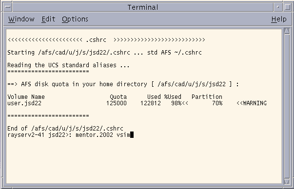
1) Starting ModelSim in Linux Environment: After logging in Linux system as we did in previous class type mentor. This command will show all tools available on afs systems. Specifically for invoking ModelSim type mentor vsim as shown in figure below at command prompt
2) Creating Project: After invoking ModelSim main window will popup on screen. Now you have to create a VHDL project in which you will store all your design related VHDL files. Go to file and click on project following window will appear on screen. in this particular case a previous project is opened, as you create a new project it will as whether to close the present project or not.
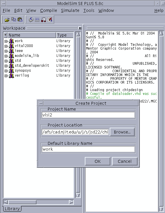
Enter project name in given field, give project location. Let the default library as work. Click OK.
3) Writing VHDL code: After creating project its time to write VHDL for specific functionality. For creating a VHDL follow the following squence
File-->New-->Source-->VHDL
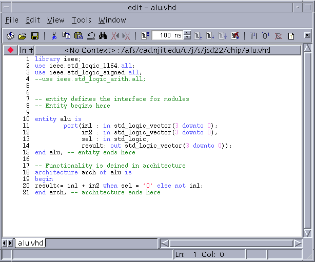
This will open up a editable window in which you can enter VHDL description for your system. After writing the code save code as filename.vhd ( filename can be any OS allowed alphanumeric combination ) and add it to current project. At end of this step the window will look like following
4) Compiling VHDL Code: After writing the code and saving it in desired directory, it is
compiled to check for any syntax error. Click on compilation symbol
 to compile
individual files. All files in batch can also be compiled simultaneously by
clicking on "compile all" button. Due to wrong syntax some errors could occur.ModelSim window with errors is shown below, the compilation will not
complete unless you resolve all errors.
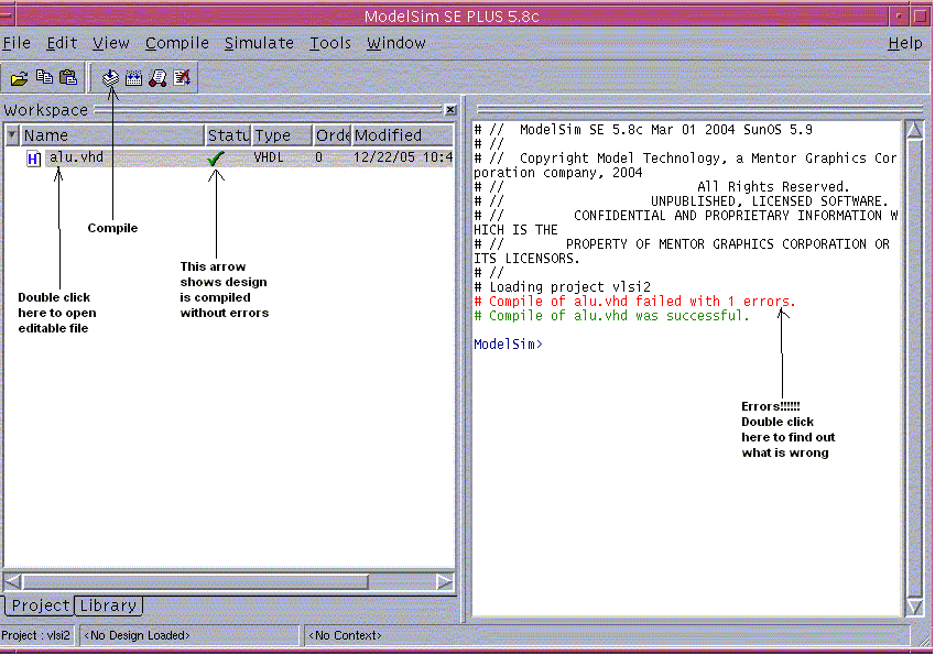
After resolving the error the compilation will succeed and will show message in green color as shown in above figure.
5) Simulation: Last step of this process is to simulate the code by applying right combination of inputs. To simulate your code go to simulate tab in main ModelSim window and press simulate. Following window will pop up. Choose your design entity within work directory, press OK. Here we chose alu within work directory. Simulation option can be changed by going to Simulation Options. You can change radix to hexadecimal which is appropriate for vectors. Choose Run time according to your requirements or let it default.
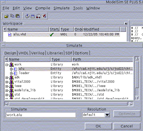
After simulating the code go to view tab and select wave, this will open a new window in which waveforms will appear. Windows for variables, signals and dataflow can be open in same fashion. Go to signal window and follow the following sequence add-->wave--->signals in design. By doing this all signals will appear in wave window.
After getting signal in wave window, right click on signal and select force, force input signals to desired values. Clock signal can also be applied by using same sequence, choose clock instead of force.
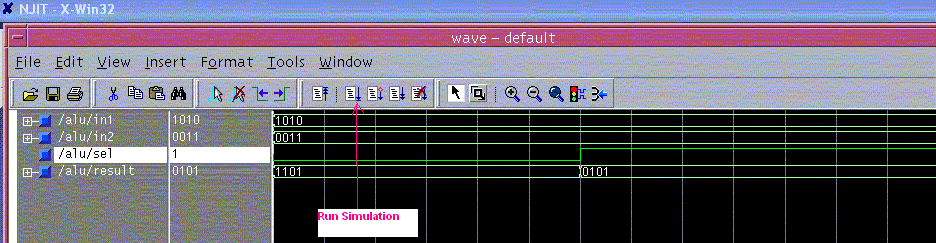
Run simulation by pressing the run button. The window will look like following. Verify the results visualy. If you are not getting the desired functionality repeat whole process of compilation and simulation after making changes in code.
NOTE: .do files can be used for big simulations.