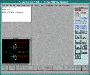
 If you are doing the post-layout simulation, you
will get to see the annotations (in red color) that IC extract placed on
your schematic.
If you are doing the post-layout simulation, you
will get to see the annotations (in red color) that IC extract placed on
your schematic.This document contains a step-by-step tutorial for simulating an inverter in the Mentor Graphics application Accusim. Separate documents began the tutorial for other Mentor applications.
Once you have a design schematic entered in Design Architect, and you wish to run an analog (SPICE) simulation of your circuit to check rise/fall times and/or delays, you need to run AccuSim II. Accusim is an analog simulation tool that runs a SPICE kernal similar to most other SPICE simulation software, but it interface directly with your schematic from DA. Once you have created the viewpoints for a cell, you can open that cell in Accusim, set inputs to the schematic pins, select from various analysis types, and perform analog simulation. This is generally done to confirm timing and power specification for your cell. You can simulate directly from your schematic to check functionallity, or you can simulate the extracted results from layout which will include parasitics and give an accurate timing analysis.
To open Accusim,
first open Mentor Design Manager
> mentor.2002 dmgr &
which will launch design Manager. Double Click on the "Accusim" icon in the left hand side tab to open the accusim dialog box. Select the view point of the design you want to simulate and click Ok.
Once
AccuSim II is loaded, you should see your schematic.
 If you are doing the post-layout simulation, you
will get to see the annotations (in red color) that IC extract placed on
your schematic.
The first thing that we need to do is to tell the simulator what transistor models you want to use.
Download the model file for TSMC 0.35mm process - tsmc035.mod
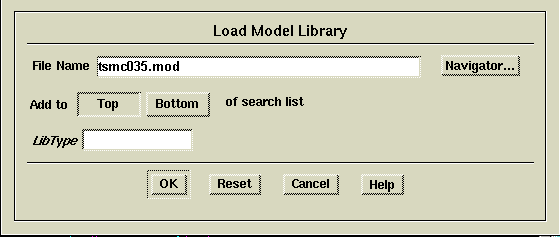
To load
a model file, select
File > Auxiliary
Files > Load Model Library
from the
main menu. In the File Name box of the
window that opens, enter
tsmc035.mod
to select the models for the
TSMC
0.35mm
process. You do not need to set any other options in this dialog
box, so click 'OK' to complete this selection.
Return to your schematic
window; size this window as desired and zoom to view all of your
schematic (shift-F8). The DC Mode
palette should be active on the right side of the Accusim screen.
If you need to change VDD to 3V from its default value of 5V. To
change this, select (i.e. click on) the VDD symbol of your schematic.
This will highlight the entire net attached to VDD. From the DC
Mode palette, select
ADD
FORCE
In the window that opens, set the force as a DC voltage
of magnitude 3 volts then click 'OK'. A circle appears in the
schematic window near VDD showing the port forced (VDD) and port
referenced (GND). Even if the schematic shows the VDD symbol with
5V, the actual force(voltage) is only 3V.
Next,
we must tell the simulator what type of simulation to perform.
From
the DC Mode palette select
SETUP
ANALYSIS
Alternatively, you could select from the main
menu
Setup > Analysis
We wish to see how the circuit operates
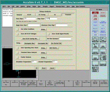
over time with different inputs, so we will perform a transient analysis. In the Setup Analysis window, press
the Transient
button to get the dialog box for setting up a transient analysis.
Now set
Time Step =
1N (for 1nsec) and
Stop Time = 100N
Leave everything else at its
default value and click 'OK' to complete this
step.
 Notice
that the palette is now set to Time Mode (no
longer DC Mode) since you have requested transient analysis. Now
you should set the input forces. In your schematic, select the
input signal in and
then add a force by selecting
ADD FORCE
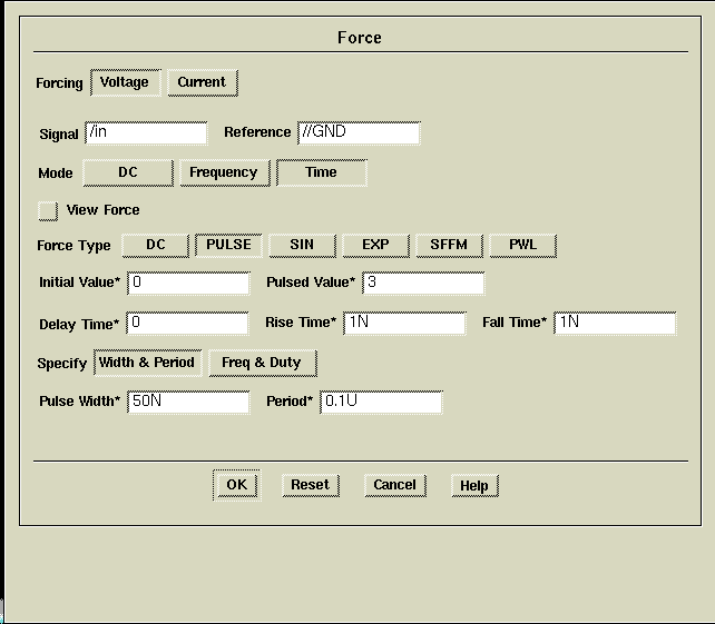
from the Time Mode palette. In the Force
window (figure on right) set this force a Voltage in Time mode.
The Force Type is PULSE with
Initial Value = 0 (volts)
Pulsed Value = 3
leaving
the Delay, Rise, and Fall times as default values. Next, specify
the Width and Period of the input signal as
Pulse Width = 50N (nsec)
Pulse Period = 100N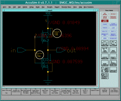 then click
'OK' to finish this setup step. Your schematic should now
look like the figure to the right.
If you had multiple inputs, you would add others using the steps above,
varying the timing as appropriate to test the desired operation.
Notice that a variety of options are available such as sine waves (SIN)
and piecewise linear (PWL), just like in most SPICE
programs.
Next
you need to select which signals you want to display. Typically
this would include all the inputs and outputs that you will view to
verify circuit operation. First unselect all to remove any
previous selections. Then select the input in and
the output out. From the Time
Mode palette, select
TRACE and
LIST
and a trace and list window will open to display your
selected signals.
Now,
with your mouse over any Accusim window, type
run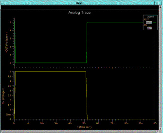 to run
the simulation (or you can use Ctrl-F1). You
can ignore the warning about the version parameter in the model being
ignored. After running the simulation
(which will be very quick
for the inverter cell, but can take a while for more complex circuits),
a Chart window will display your results. You can zoom in and out
using options from the View menu. For example, to zoom in,
select
View > Zoom In > As Specified
and specify the desired
magnification. Play around with viewing your results, and don't
forget to checkout the right-click menu options.
Observe
the results of your simulation and ensure your circuit is functioning
properly. If not, you will need to go back to DA and
correct your schematic until it works right. If you make any
alterations to your schematic, when you return to Accusim
you should update by selecting from the main menu
File >
Design > Load DA Changes 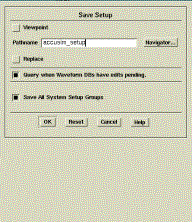
Once
your simulation is working properly, save your setup for use later. Do
this from the main menu selecting
File >
Simulation > Save setup data only
and giving a descriptive
name like "accusim_setup".
Once
saved, you can load this setup later by selecting
File >
Simulation > Restore setup data
and then choosing the
"accusim_setup" file in the pathname box using the
navigator. After
you enter 'accusim_setup', leave everything else to default and click
'OK'. A dialog box pops up with a question whether you wish to
continue.
Select 'yes' and a trace window appears with /in and
/out graphs but no traces are seen. Select /in and /out ports from
the schematic and click 'run' from the 'time mode palette menu' on the
right. Now the traces can be seen if you have saved the setup
earlier.
Measuring Circuit
Parameters:
Several
useful functions like rise time, fall time etc. can be found after
running the functionality-check simulation. From the Time Mode palette, select
RESULT
From the Result menu, select
the button
WF
Measure
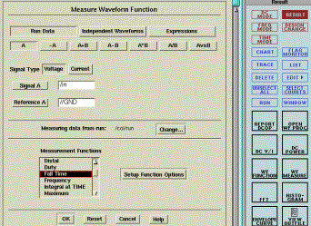
This will open a Measure Waveform
Function window as shown below. Signal
A is by default set to port 'in' (/in). Replace this with
/out, so we can measure features of our output node.
The dialog box also gives a list of measurement functions that the
simulator can provide -information like rise time, fall time, slew rate,
average, RMS, duty, overshoot, undershoot, settling time, DC Operating
Point (DCOP) etc. As shown in the figure below, select
Fall
Time
and then click ‘OK’.
A Report Measurements window (see figure below) will
then be displayed showing the Fall Time of the /out signal. Leave
this window open and select
WF
Measure
again (from Time Mode > RESULTS palette). This
time scroll through the list and select the Rise
Time for the /out signal and click
'OK'. Now both Rise and Fall Time should be in your Measurements
Report as shown below (note this figure also shows results for /in
although you have not been asked to check these).

You can use the WF Measure function to measure many different results from your simulation. For this assignment, only Rise and Fall time are required. Your Rise and Fall time should both be near the values shown in the figure above (~1.7nsec). If they are significantly different, you should check your circuit and resimulate. To check this assignment, we will make these measurements on your circuit and confirm proper timing.
11.
Exit Accusim -you're all done!
This was just a small sample
of how and why to perform analog simulations. As designs become more
complex, parasitics can become a major factor and proper simulations are
required.