From IC Station, after your layout has passed DRC and LVS, you are ready to backannotate parasitics for simulation. This means you will get IC Station to determine the parasitics based directly on the physical layout you constructed, and you will use this extracted information to perform very accurate analog simulations using Accusim (described in the next tutorial). We will be using what is called a 'lumped extraction' which means we will extract parasitics (e.g., capacitances) and lump-together (sum) the value at each node in our circuit. Thus, each node will see the same RC delay no matter where you are on the node. Note, this will not work for analysis of transmission lines, but is sufficient for most timing analysis in digital circuits.
To
prepare for extraction, be sure your cell is reserved for edit.
Every time you save your cell, you will need to reserve it for
edit. Anytime it isn’t reserved, click
File > Cell > Reserve >
Current context.
From
the main palette, select
ICextract (M)
Select
Load Rules from the palette
menu to load a rules file that includes data needed for Accusim
extraction. Specify the file
/class/lib/564.rules
Extracting
Lumped capacitances:
Now select Lumped from the ICextract palette to display the extraction dialog box.
In the
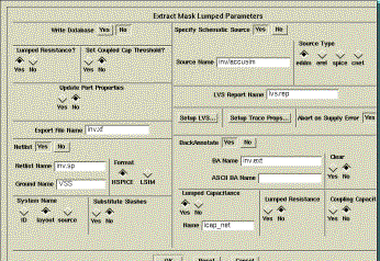
Extract Mask Lumped Parameters window click 'Yes' next to Specify
Schematic Source. Then enter the Source Name, which is
related to the name of your schematic cell. Enter the name as
<cellname>/accusim, which will select the required
accusim viewpoint. There is no navigator here, so you'll
have to enter the path to the accusim viewpoint. For this
tutorial, enter
inv/accusim.
If you have the sdl
viewpoint open, you need to close it, first using
Logic >
Close
from the IC Extract (M) palette.
Click 'Yes' next to BackAnnotate to specify that you want to backannotate the results.
Specify the name of the file for the backannotation results in the BA Name slot. The default is lumped, but you need to change this to <cellname>.ext, which will be saved in your home directory. If you use the same file name for subsequent extractions, you last extraction will overwrite the previous one provided you should select 'Yes' under the Clear option.
Complete
this window by selecting the following options:
Lumped Capacitance = No
Lumped Resistance =
No
Coupling Capacitance =
Yes
Name = cpl_cap_net
so that your window
looks like the figure below. These selections will use the
cpl_cap_net property for net capacitance between a nodes. Since
this property will override the cap_net property (which is just the
intrinsic capacitances) we turn off the Lumped Capacitance
extraction. Lumped resistance is not used in Accusim, so no
point in extracting it either.
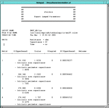
On the left side of the dialog box, fill in the Export File Name as <cellname>.xf, so you should enter inv.xf. Select ‘Yes’ for the Netlist option. Leave the default netlist format at ‘HSPICE’. Under Netlist Name enter <cellname>.sp and fill in the Ground Name with the name you used in your layout (VSS/ground/GND). The SPICE Netlist gives the lumped capacitances while the Export File gives the resistance and capacitance of each net as shown in the figure below.
Click on ‘OK’ to accept this dialog box and extraction will begin. When the extraction is done, you will see that your schematic is automatically updated and you will see the annotations on it.

Open the export file and netlist
file from the main menu:
MGC >
Notepad > Open > Read-Only (or Edit)
Click on the
navigator button to load the file
( inv.xf) and click ‘OK’.


Distributed
from the IC extract(M) menu. This opens the
Extract Mask Distributed Parameters window.
Set the timing delay analysis to default for ‘Penfield’ and enter the export file as inv.xfd. Set
everything to default as shown in the figure.
Accept the dialog box (click 'OK') and the following message should appear at the bottom of the screen:
‘LICENSE FOR IC
EXTRACT RC HAS BEEN RELEASED’
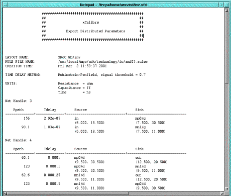
Open the export file (inv.xfd) using
MGC >
Notepad > Open > Read-only (or Edit)
This analysis gives
the measurement of all the timing delays and resistance of each path of
a net.

To view any net in the layout, go to
IC trace(M) menu and run LVS then select
Show > Nets by
ID
in the IC trace(M) menu. When you enter the number e.g.
1 or 2,…. The corresponding net is highlighted. To unshow it, select
Unshow > All
nets
which removes the highlighted region. We will
use this data in later assignments to measure timing characteristics of
our circuit.
This completes the Extraction Tutorial.