Easy Edit Menu:
From the
IC Palettes menu click on Easy Edit. This causes the IC Palette to be
replaced by an edit menu which contains many editing functions that you
may need. Many of these functions are explained below.
Additional edit functions can be found in the Expert Edit palette like the
Move Edge tool described below.
Note, LMB
below refers to 'left mouse button'.
Add Shape:
Click on
Shapes in this menu. A pop up dialog box appears on the bottom of the
layout window. It indicates the current command that has been invoked. On
the layer palette in the upper right hand corner of the IC Station window,
click on the metal1 (CMF) layer with the LMB. This selects metal1 as the
current layer for the next shape to be drawn. In the layout edit window
you now see that the cursor has change shape to a cross. Keeping the LMB
pressed, drag the mouse till you satisfactorily draw the shape. You
should see a blue highlighted rectangle. To unselect this shape, press the
F2 key. To reselect this shape place the cursor on the shape and press the
F1 key.
In
general, F1 selects the nearest unselected shape whereas F2 unselects all
selected objects. To clearly identify a selected shape it is always
highlighted.
Delete:
If you erroneously enter an incorrect shape, select it and then
click the LMB on Delete in the Easy Edit menu. Click on OK in the dialog
box that appears at the bottom of the window. This causes the selected
shape to be deleted. You can also simply hit the Delete
key on your keypad and everything selected will be deleted.
Undo:
You
can undo the previous operation by clicking on the Undo in the
palette. You can also, while you mouse is over the layout window,
just type 'undo' and hit Enter.
Copy:
Select the shape to be copied. Then click on Copy in the Easy
Edit menu. Click on OK in the dialog box and you should then see a ghost
image of the selected shape, which is dragged about with the mouse. Place
it at the correct location and click the LMB to fix the position of the
copy. You will still see the ghost image and so if you wish you can copy
it to yet another place. When you are done copying press the F2 key and
all copied shapes will appear in their new locations.
Rel Copy
is used to copy the selected shape for the known displacement along X and
Y axes. Select the shape, click ‘rel copy’ , fill in the offset values and
click ok.
Move:
This
feature is similar to copy except that the original shape does not stay in
place. Place F2 at the end of the move to fix the location of the shape.
Rel Move can be used if you desire to move along known displacement along
X and Y axes. Select the shape, click ‘rel move’ and fill in the offset
values and click ok.
Notch:
This feature is used to edit shapes that are in the right place
but are of the wrong shape or size. Select a shape using F1. Assume that
the shape is smaller along one dimension than it needs to be. Click on
Notch in the Easy Edit menu. Click OK in the dialog box. Now, position the
cursor on the boundary of the selected shape and keeping the LMB pressed,
drag the cursor to form a box that represents say the additional size that
the shape needed to be. Release the mouse button and you should see that
the shape has now increased to the desired size. You can similarly reduce
sizes , add different shapes etc. using the Notch command. The one
important thing to keep in mind is that before notching i.e. dragging the
mouse with the left button pressed - you must position the mouse on the
edge of the selected shape.
Stretch:
This feature is used to increase or decrease dimension of an
edge. Click on Stretch in the Easy Edit menu. Select an edge. Drag the
edge with your LHM to the desired position.
Flip:
Any shape can be flipped about any axis. Select the layer or
an area, click flip in the easy edit palette and with LHM presses, draw
the axis about which the shape needs to be flipped.
Align:
Select the area to be aligned to a target object. Click
‘align’. This changes the mouse pointer, that when clicked at the target
object pops up a window as shown. Select the directions of source and
target objects to be aligned and if needed, fill in the offset value.
Click ok.
Rotate:
Select
the shape to be rotated and click ‘Rotate’. A dialog box appears at the
bottom of the screen and the angle to which the selected shape to be
rotated is to be written. Click ok.
Expert Edit menu:
A useful
feature in the expert edit menu is the move edge function, MVED+.
It functions as both stretch and move command. By selecting a edge of a
polygon, the MVED+ function
as “stretch”. On the other hand, by selecting the whole polygon, MVED+
function as “move”. Once you turn on MVED, clicking on
the screen will no longer select the nearest object, but it will select
the nearest edge, It's confusing at first, but many people find a
combination of MVED and notch will do almost all edit functions
needed.
Using the
Layer Palette:
 Adding shapes is one of the most common
activities, but selecting layers from the ADD SH dialog box can be
cumbersome. To ease this task, you can add a layer
palette at the right hand top corner of the screen which contains
all of the layers you need and can be easily edited to add/remove other
layers. From the main menu, select
Other > Layers
> Show layer palette
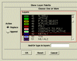
In the dialog box that appears you
will see a list of all the layers for the chosen process. Scroll
down the list to find the layers you will need. First, select layer
number 42 i.e. N_W, click it and by holding the
control key (on the keyboard), select the other layers you need (from
layer number 43 to 49). Once all the layers from 42 to 49 are selected,
click ‘OK’.
 If you happen to miss selecting few layers in your
first attempt or you need any additional layers, you can always go
to
Other > Layers > Append to the layer
palette
which opens up the same dialog box and
you can add additional layers to the existing palette by selecting them as
explained above and clicking ‘OK’.
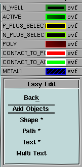
Once the layer
palette is chosen, it appears at the right hand top corner of the screen
above the easy edit menu as shown here to the right.
If at any point you wish to
hide/delete the layer palette, go to
Other >
Layers > Hide layer palette
and it
disappears.
The layer palette is used to
pre-select the layer that will be drawn when you use the
Easy Edit >
Shape
command to add a shape to your layout window. Just
click on the desired layer from the layer palette, click on Shape
in the palette, and start drawing the layer you want.
Useful Macros:
To use any of these commands, simply
type them in the cell window. A prompt bar will appear with your command
in it.
Function
|
Description
|
|
pc |
Place a poly contact; places a
poly contact centered at the current cursor position.
|
|
pp |
Place a port contact; creates a
port and places it where you click. |
|
nwc |
Place an n-well contact;
creates and places an n-well contact on the standard cell power
rails. |
|
pwc |
Place a p-well contact; creates
and places p-well contact on the standard cell power rails.
|
|
p |
Place a poly path of width 2
(minimum width); Prompts you to place a poly path.
|
|
m |
Place a metal1 path of width 3
(minimum width); Prompts you to place a metal1 path.
|
|
v |
Move unconstrained; Moves the
selected object(s). |
|
ec5 |
Lumped, mask extraction for AMI
0.5; This command scripts the extraction to a specific location that
probably does not exist at your site. Modify this command if you
wish to use it. |
|
rab1 |
Remove metal1 blockages; This
command will remove all metal1 blockages in your cell.
|
|
s5 |
Set cell process to AMI
0.5 |
|
cp |
Checkpoint cell; save the cell
and then reserve the cell. |
|
dup |
Delete unplaced ports; If LVS
reports unplaced ports but you see that they are all placed from
your schematic, the database might have duplicate ports. This
command will remove them. |
Back
to Top
 Adding shapes is one of the most common
activities, but selecting layers from the ADD SH dialog box can be
cumbersome. To ease this task, you can add a layer
palette at the right hand top corner of the screen which contains
all of the layers you need and can be easily edited to add/remove other
layers. From the main menu, select
 If you happen to miss selecting few layers in your
first attempt or you need any additional layers, you can always go
to