| Physics 320 |
Astrophysics I: Lecture #3
|
Prof. Dale E. Gary
NJIT
|
Telescopes and Detectors
Lenses, Mirrors and Optics
Telescopes come in two basic types: refracting telescopes (using a lens as its main element: 1, 2, 3 ) and reflecting telescopes (using a mirror as its main element: 1, 2, 3). Simple ray tracing
techniques exist for determining for a given optic (either a lens or a
mirror) where an image forms, given an image distance. The method
is illustrated in the diagrams below.
 Geometric optics ray tracing
for a thin lens. Given the focal distance f, and the
object distance do,
one can determine the distance to the image di,
geometrically.
The rules are: parallel
rays go through the focus, and rays through the center of the
lens do not bend. |
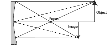
 Geometric optics ray tracing
for a mirror works the same way. The rules are:
parallel rays go through
the focus, and rays that hit the center of the mirror
bounce off symmetrically. |
The relationship between
focal distance f, object distance
p,
and image distance q,
is given by the formula:
1/f = 1/p
+ 1/q
which can be verified as consistent
with the above rules through simple geometry (homework problem 6.2). Another important formula is the lens-maker's formula:
1/fl = (nl - 1) (1/R1 + 1/R2)
where nl is the index of refraction at wavelength l, and R1 and R2 are the radii of curvature of the lens (negative radius for a diverging lens). Note that this formula assumes the lens is in a vacuum (works approximately for air). If the lens is in a medium with index of refraction n0, then the first term in parentheses on the right should be (nl - n0)/n0. Note that the index of refraction depends on wavelength (see http://refractiveindex.info/), so in general a lens will have a different focal length for red light (l ~ 750 nm) than for blue light (l ~ 450 nm). This causes chromatic aberation, which can be combatted by using an achromatic doublet, or an apochromatic triplet lens. An important property of mirrors is that all wavelengths are reflected the same, so mirror-based telescopes do not suffer from chromatic aberation.
An important number for a telescope's main
lens or mirror (called an objective),
is its f ratio, which is simply the
ratio of the focal length to the diameter D
of the objective
f ratio = f/D.
In the above diagrams, the f
ratio is about 1, but for optical telescopes it is more typically about
10. (For radio telescopes, it is usually less than 1, typically 0.4.
Why do you think that might be?)
The arrows in the above drawings
represent an extended object, which covers some angular distance in front
of the lens. If this were the Moon, say, it would cover 1/2 degree
in the sky. When we make an image, it also covers some angular distance
from the lens, and if we place a detector there (say a piece of photographic
film), the image will have some linear size. Now, the Moon can be
considered to be at infinity (that is, do
is much larger than di),
so the image of the Moon will occur at the focal distance f
(which is why it is called the focus). In this case, the linear size
per degree of angular size of the image at the image plane (called the
plate
scale) is simply
s = 0.01745 f
where the constant 0.01745 is
just the number of radians in a degree, and f
is the focal length of the objective. The linear size of an image
will be sa,
where a
is the angular size of the object in degrees.
Example:
Say we have a telescope
of 8 inch aperture, and f ratio
of 10 (also referred to as f / 10).
How large will the Moon's image appear on a piece of photographic film
at the focus?
The focal distance f is 80 in, so the image will
be
sa = 0.01745
a
f = 0.01745 (1/2 degree) (80 in) = 0.7 in
Telescopes
You will often hear
someone ask, "What power is that telescope?". This is a relatively
meaningless question, and indicates someone who does not understand the
principles of optics. Do not be one of these people! Their
confusion is understandable--low-end telescopes are often advertised by
their "power," by which is meant their magnification factor.
You will never see a true astronomical telescope advertised this way.
What is really important is the light-gathering
power of a telescope, not its magnification. The light-gathering
power is important, because this is what limits how faint an object one
can see. The larger the area of the objective, pD2/4,
the larger the amount of light gathered. The light-gathering power
is not a fixed number, but is expressed in comparison with another optical
system, say your eye. Your pupil has a maximum size of about 0.5
cm, so the light-gathering power of an 8" telescope (diameter 20.3 cm)
is
LGP = (20.3/0.5)2
= 1650.
The main function of the telescope is to take all of this light and concentrate it into your eye (or an equivalent camera). In this case, a telescope would gather 1650 times as much light as your naked eye. A second important measure of
a telescope also scales with its aperture--the resolving
power. This depends on the wavelength of light that we
are trying to image, and is given in angular units, arcseconds, by
RP = 1.22 (206265 l/D)
arcsec
where the constant 206265 is
the conversion factor from radians to arcseconds. The factor of 1.22
is due to the fact that the aperture is circular. For a rectangular
aperture the factor would be 1.0, but grinding rectangular lenses is not
easy!
Example
What is the resolving power
of our 8" telescope in the optical (l
~ 500 nm)?
8" is 20.3 cm, or 0.203 m, so the resolving power would
be:
RP = 1.22 (206265 l/D)
= 1.22 (206265)(5x10⁻⁷ m/0.203 m) = 0.62"
Note, however, that the atmosphere
usually limits the resolution to about 1", so having a telescope much larger
than 8" does not help in resolution unless we either are above the atmosphere
or can correct for the atmosphere. A larger telescope does,
however, help in light-gathering power.
What about magnification?
As it turns out, any telescope can be any magnification power! It
does not depend at all on the aperture, or size, of the telescope.
The magnification only depends on the ratio of the focal length of the
objective f and the focal length
of the eyepiece fe:
MP = f / fe.
Common eyepieces for telescopes
are 26 mm and 12.5 mm. An f/10 telescope of 8" aperture (203 mm)
would provide corresponding magnifications of 78X and 162X for these two
eyepieces. However, you could get the same magnifications with a
2" telescope simply by using eyepieces of 6.5 mm and 3.1 mm focal length.
This is why asking what "power" a telescope has is not too meaningful.
Any telescope can have any power, depending on the eyepiece you choose.
However, there is an important
relationship between light-gathering power and magnification, which makes
higher magnifications useless for small telescopes. Think of the
objective as gathering light, and the eyepiece as spreading it out again.
Although you can spread the light out indefinitely with smaller focal length
eyepieces, this reduces the brightness of the image until you reach a point
where you cannot see it any longer. This happens sooner, of course,
for a smaller telescope, which gathers less light in the first place.
If you want to observe a faint, extended nebula, smaller powers are best
(you see more of the sky at once, and the nebula is brighter). If
you want to observe a brighter object, like the Moon or a planet, you can
often get away with higher power. However, there is no point magnifying
the image beyond the resolution of the telescope (or the atmosphere), since
you will just magnify the distortions.
Detectors and Image Processing
Three
types of detectors have historically been used in optical astronomy:
-
Photographic Film
- Photomultiplier Tubes
-
Charge-Coupled Devices (CCDs)
The last type, the CCD, has
for most applications replaced the other two (even in ordinary photography, with the rapid advances
in digital cameras). One reason is "quantum
efficiency" or QE. This expresses the ability of the detector
to respond to photons, or light-quanta. The human eye has a QE of
about 1%, meaning that for every 100 photons that fall on our retina, only
one is detected. Photographic film has a similar QE, about 1%.
Photomultipliers have an efficiency between 10 and 20%. In contrast,
CCDs have much higher efficiencies, close to 100% in the red region of
the spectrum.
Another reason for
the increasing importance of CCDs is the large form-factors now available--up
to 10 million pixels (e.g. KAI-11002 chip, 4008 x 2672). It is common in astronomical detectors to place multiple CCD chips side by side for extremely large format images (e.g. the SDSS camera, LSST camera).
CCDs have other advantages
as well. They are linear devices, so that they give a precise measure
of the number of photons falling on each pixel, over a very large range
in brightness. Ultimately, however, the pixels (quantum wells) will
fill up, and the device saturates. The electrons then spill over
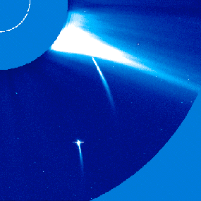
into neighboring pixels. The image below shows an example of such
saturation.

Two Sun-grazing comets plunge
to their fiery death
into the Sun. The
image of one of the comets has
saturated the CCD camera,
and its light spills into
neighboring pixels, making
a horizontal line artifact.
CCDs also have the advantage
of being purely digital, so they can be controlled easily with computers,
and their data can be manipulated digitally.
Signal to Noise
Photons obey Poisson
statistics, meaning that the arrival of photons into a given pixel is a
random process, but always positive (there are no negative photons).
The statistical fluctuations in the mean number of photons <N>
have a standard deviation given by s
= <N>1/2.
Thus, the signal to noise ratio is
S/N = <N>/s
= <N>1/2.
Now, the mean number of photons detected
by a CCD pixel will depend on the photon flux fp
(photons per second) x the integration time Dt
x the quantum efficiency, so the signal to noise becomes:
S/N = (QE fpDt)1/2.
For a given quantum efficiency,
we can increase the signal to noise by increasing the integration time.
However, to double the S/N, we must increase the integration time by a
factor of 4.
An Example--The NJIT
Observatory
The NJIT
observatory has a computer-controlled 10" Meade LX200-GPS telescope.
We can use this telescope with an SBIG STL-1301 CCD camera for "deep-sky" imaging, or use a simple webcam for planetary and lunar imaging. The telescope is an f/10 system, and the two CCD cameras have the
following specifications:
Some CCD Camera Specifications
| CCD |
Kodak KAF-1301E |
TouCAM II VGA CCD |
| Pixel Array |
1280 x 1024 pixels
20.4 x 16.4 mm |
640 x 480 pixels
3.58 x 2.69 mm |
| Total Pixels |
1,310,720 |
307,200 |
| Pixel Size |
16 x 16 microns |
5.6 x 5.6 microns |
| Full Well Capacity (NABG) |
~120,000 e- |
? |
| Dark Current |
0.5e¯/pixel/sec at -30° C |
? |
What is the image scale of the KAF-1301E
CCD (arcsec/pixel)?
The focal length is f = (f ratio)D
= 10*10 in = 100 in. <= note these are inches!
The plate scale is s = 0.01745 f = 1.75
inches/degree.
One pixel is 16 microns, so this corresponds to an image
scale of
(16 x 10-6 m/pixel)(3600"/degree)/[(1.75
in)(2.54 x 10⁻² m/in)] = 1.29"/pixel
What is the field of view of
the CCD camera, in arcminutes?
The chip has 1280 x 1024 pixels, and each is 1.29",
so this becomes 1659" x 1321", or in arcminutes: 27.6' x 22.0'.
Will the Galilean moons of Jupiter
fit into the field of view when Jupiter is at opposition?
At opposition, Jupiter is 4.2 AU from Earth,
and is 71,400 km in radius. This corresponds to an angular size,
in arcsec, of 206265 (R/d) = 23". The outer-most Galilean
moon is Callisto, at 26.6 Jupiter radii, or 618". This is smaller than the CCD field of view, so Jupiter and its moons will fit comfortably in the field of view. The planet would cover about 36 pixels of the image.
A sampling of images
taken by students with this system can be found here.
Note that there is a whole
host of other issues involved with taking good images, involving background
sky brightness, flat-fielding, and compensation for image motion.
We use the webcam for taking images (and movies) of the Moon and planets, because it has a far smaller plate scale (i.e. produces more magnified images). If the weather cooperates, we will have an imaging session this week.
Spectroscopy
Spectrographs are
used to split the light from an object into its separate wavelengths, or
colors. One can determine the temperature of an object, for example,
from the shape of its blackbody spectrum. In addition, many objects
emit spectral lines (narrow regions of the spectrum that are brighter than
the background--emission lines; or darker--absorption lines). By
identifying these lines we can determine what the object is made of, and
by measuring them we can determine the temperature, density, and speed
(through the doppler effect) of the objects. The spectrograph is
an important tool of Astronomy.
The most common type of spectrograph
is the grating spectrograph, which uses a diffraction grating (basically
a set of extremely closely-spaced ruled lines). Diffraction at the
edges of each space between the lines causes the light to be split into
its component colors, and interference of the light from each set causes
the spectrum to be split into "orders". For a simple grating, higher
orders are fainter, but the light into a particular order can be increased
by "blazing" the grating (kind of a saw-tooth profile) at the appropriate
angle.

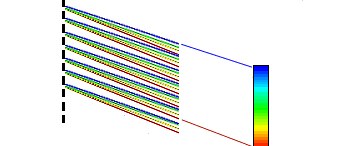
Diffraction into a high
order. In the direction shown by the blue lines,
the blue light interferes
constructively because the beams all arrive at
the distant screen after
having traveled distances different by an integral
number of wavelengths.
In the direction shown by the red lines, blue
light will arrive after
traveling non-integer multiples of the wavelength,
so the light interferes
and the intensity drops to near zero. However, red
light arrives after traveling
distances different by an integral number of
red wavelengths, so the
red intensity is high in that direction.
As shown above, the direction
for constructive interference into order m
is given by
sin q = ml/d,
where d
is the spacing between ruled lines on the grating.
What We Have Learned
The important formulas
and quantities for telescopes are:
-
Image formula
1/f = 1/do + 1/di
- Lens maker's formula 1/fl = (nl - 1) (1/R1 + 1/R2)
- f Ratio
f ratio = f/D
- Plate scale
s = 0.01745 f
- Light gathering power
LGP = (D/deye)2
- Resolving power
RP = 1.22 l/D (radians)
-
Magnification factor
MP = f / fe
Another important formula is
Signal to Noise ratio for CCDs:


