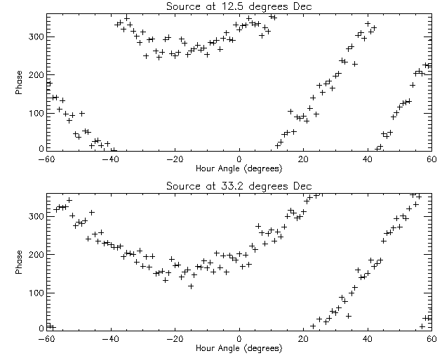
7.1 The figure below displays the phase at 5 GHz as a function of hour angle (from -60 to 60 degrees) for two different sources, one at 12.5 degrees declination and one at 33.2 degrees declination. The phases were measured with a baseline error (ΔBx, ΔBy, ΔBz), but no source position error. The data used to make this plot are in an IDL save file that can be downloaded from here, or a simple text file from here (columns are hour angle [degrees], phase at Dec 12.5 [degrees], and phase at Dec 33.2 [degrees]). There are three arrays in the save file, h (hour angle), p12_5 (the phases for the source at 12.5 degrees declination) and p33_2 (the phases for the source at 33.2 degrees declination). Using any means you wish, determine the baseline error from the data (i.e. determine the values of ΔBx, ΔBy, and ΔBz, in m) and plot the corrected data as a function of hour angle (scale your plot from 0-360 degrees). Describe the method you used to find the baseline error. Note: when you plot your corrected data, the phases should be flat, but not necessarily zero. You may require the IDL MOD function to keep your phase correction between 0 and 360. Hint: Look at the dependence of Eq. 3 of lecture 9 on hour angle.

Phases measured with a baseline error, but no source position error, for sources at two declinations.