|
EE291 - LABORATORY III
THE SUPERPOSITION PRINCIPLE
AND THE THEVENIN EQUIVALENT CIRCUIT
OBJECTIVES
1. Verifying experimentally the superposition principle for a
circuit with two voltage sources.
2. Designing and testing the Thevenin equivalent circuit.
PRELAB
1.
Make a brief plan of
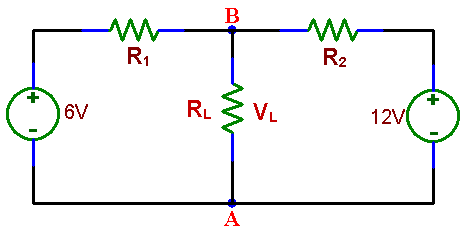
measurements to demonstrate the superposition principle for a circuit shown in
Fig. 1.
2. Draw a Thevenin equivalent
circuit of the circuit in Fig. 1 without RL, which is an external
"load" resistor.
Express the voltage of the source and the resistance
in the Thevenin circuit in terms of R1 and R2.
LABORATORY
Equipment needed from the
stockroom: EE291 parts kit, a
proto-board, a resistance substitution box, leads.
1.
THE SUPERPOSITION PRINCIPLE
Assemble the circuit shown in Fig.
1. Choose different values for R1 and R2 from resistors in 1k to 30k range such
that their ratio is no more than 5. At first, do not connect the load resistor
RL.
|

|
|
Fig.1 A network of three resistors with two voltage sources
|
Measure the voltage between points
A and B, with RL infinite (open circuit):
a) With both sources in the circuit
b)
With only one of the sources in
the circuit while the other is replaced with a wire ("short circuit").
Read the warning below before making these two voltage measurements.
Warning: do not short the power
supplies when replacing it with a short circuit!
Disconnect them first from the
circuit.
c)
Repeat a) and b) after
connecting a resistor RL (in 3k to 20k range) between points A and B. After the
measurements put aside this resistor; you will need it again in part 2.
Check that the measurements a) and
b), without RL, and measurements c), with RL, agree with the superposition principle. Calculate any discrepancy in % and
comment if it is reasonable, based on the precision of your instruments.
Compare also the measured value of VL
with calculations for a circuit with two sources.
|
