IE 455 Robotics & Programmable
Logic Controllers
Abstract & Laboratory Experiments
Prerequisites: junior/senior standing or see Professor McDermott for permission
Fall Semester
Introduction to the design and implementation of programmable logic controllers for use in industry in the areas of automotive assembly, pharmaceutical manufacturing and chemical processing. Topics include ladder logic, input/output ports, continuous process control, timing and counting functions, and digital gate logic.
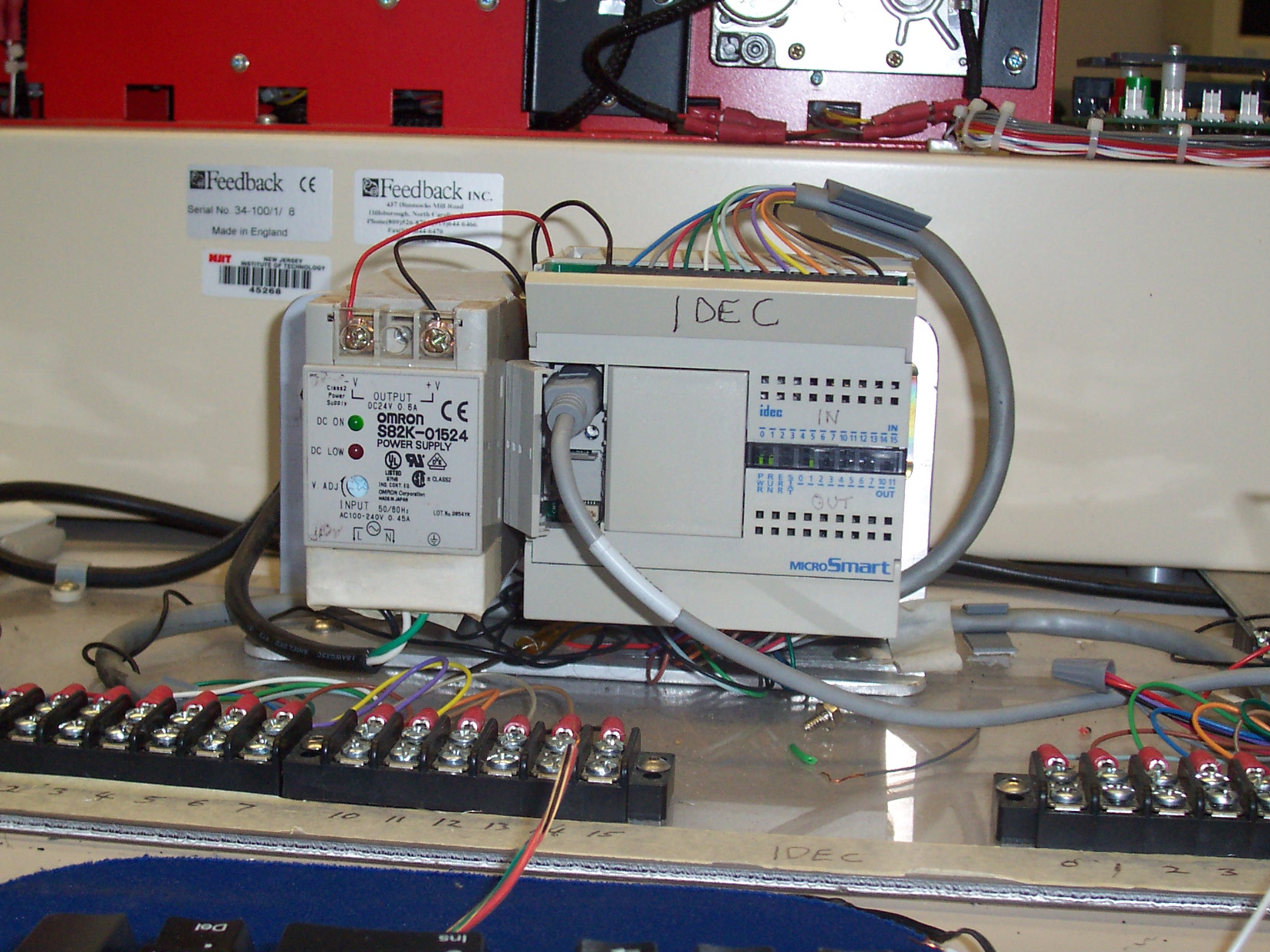
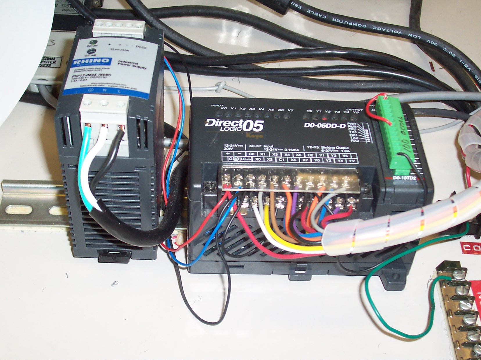
Mitsubishi Medoc PLC IDEC WindLDR PLC DirectLogic 14IO PLC
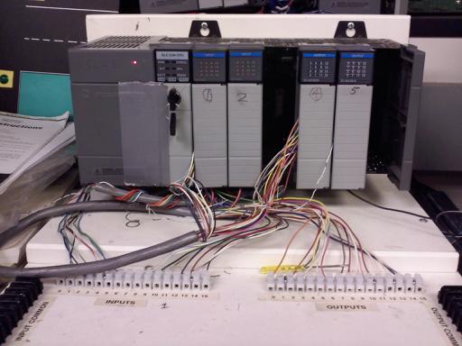
AllenBradley SLC5/04 PLC
Typical PLC Topics
Spray painting workcell
Spot welding workcell
Traffic light system
Elevator system
Home/car alarm system
Conveyor system
Laboratory Experiment # 1
Design and develop a PLC system to achieve the following requirements:
5 input ports or more
2 output ports or more
Ladder logic programming
Logical AND gate
Logical OR gate
Students will work in teams.
The laboratory experiment will be presented in class in two weeks.
Each team will prepare a concise team report on the experiment.
PLC System Procedure
1 Select process
2 List steps in process
3 Define Input and Output ports
4 Program computer using Ladder Logic
5 Download program to PLC
6 Test PLC operation
7 Wire Input and Output ports
8 Demonstrate PLC operation
9 Develop Team Report and/or PLC improvements
Laboratory Experiment # 2
Ţ Design and develop a PLC conveyor system to achieve the following requirements:
® conveyor S1 activates assembly station WS1
® conveyors WS2,WS3&WS4 activates three welding stations in parallel
® conveyor 5 activates inspection station 5
The output of conveyor 1 activates all three welding stations in parallel. When the welds are completed,manual switches are triggered to show that each welding process is completed. A delay could also be built in to simulate the welding processes.Next the inspection station is triggered and separate outputs indicate good welds or defective welds.
Ţ Students will work in teams
Ţ The laboratory experiment will be presented in class in two weeks.
Ţ Each team will prepare a concise team report on the experiment.
Laboratory Experiment # 3 Mod 1
Develop in the PLC software a ladder logic diagram that emulates the Paint Spraying Process in an automobile assembly plant.
Use a conveyor system to transport the vehicle ,and three paint spraying robots to emulate the painting process
Download the ladder logic to the PLC
Wire in the input and output devices
Check the wiring
Show the operation of the paint spraying process as it is controlled by the PLC
Use counters to determine the number of vehicles painted and timers to simulate the three different painting robots