Installation and Setup of Virtual Linux
J. Medina, R. Rojas-Cessa
Copyright (do not distribute)
Disclaimer: the authors are not associated nor
supported by the brands displayed in this guideline.
1. Introduction
This is a guide to help you set up a virtual
environment that consists of Linux virtual machines (VM) running on a
VirtualBox manager application. The guide shows you how to install VirtualBox,
and how to import and clone virtual machines into VirtualBox by using images
(.ova) files. Additionally, this guide provides you with an example of a simple
networking configuration that enables local communications between two Linux
virtual machines and an example of how these machines can access the Internet.
2. Preliminaries
Initial Requirements
Before you begin with the configuration of
your virtual environment, you MUST make sure your host computer meets the
following requirements:
· Memory: >4 GB RAM
· Disk: >30 GB Free available
VirtualBox installation
To install VirtualBox on your host computer,
go to:
DownloadVirtualBoxHereLinks to an external site.
Download and install VirtualBox, according to
your host operating system, as Figure 1 shows.
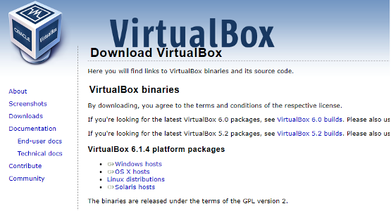
Figure 1: Download VirtualBox binaries from VirtualBox website.
After installing the VirtualBox manager
application, load a virtual machine into VirtualBox using a Linux image file
(.ova file).
Linux Images:
Two image files are provided:
· Ubuntu2022.ovaLinks to an external site.:
this is the Linux distribution we use in the lab (Recommended!!).
· Lubuntu2022.ovaLinks to an external site.: this
is a lighter Linux distribution, it demands fewer system resources than Ubuntu,
the desktop environment is a little different from Ubuntu
but it is useful for installing 3 or more VMs.
Use the external links above to download one
Linux image file, please start with Ubuntu2022.
The (Ubuntu) VM use the following credentials:
username: network
password: network
3. Setting Up a Virtual Machine
1. Open VirtualBox manager and click on the
Import icon located to the right side and under the Tools tab as Figure
2 shows.
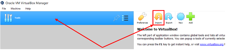
Figure 2: Import a virtual machine into VM VirtualBox Manager.
2. After you click on the Import icon,
the Appliance to import menu pops up. Locate and import the
Linux image file, i.e., the .ova file, into VirtualBox Manager, as Figure
3 shows.
Click open then next.
3. In the Appliance setting window, go to the
MAC Address Policy drop-down menu, select “Generate new MAC address for all
network adapter” and click Import, as Figure 4 shows.
The import process of the Linux image file that loads a virtual machine begins
execution.
4. Once the import process finishes execution,
a virtual machine is loaded into VirtualBox Manager. All imported virtual
machines can be found on the leftmost side menu, below the Tools tab, as Figure
5 shows.
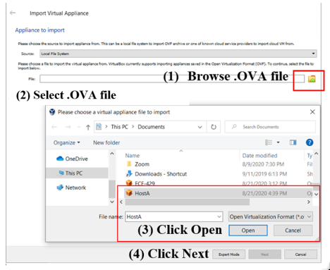
Figure 3: Import virtual appliance window.
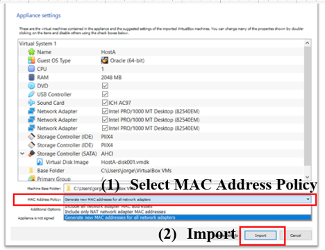
Figure 4: Appliance setting selection.

Figure 5: Virtual machines created on VirtualBox Manager.
5. Change the name of your imported Virtual
machine to ease management. To change the name of your virtual machine,
right-click on it and select the setting menu, as Figure
6 shows. Under "General" select "Basic" and
change the Name of your virtual machine. Then, click OK.
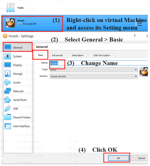
Figure 6: Virtual machine settings. Steps to change a virtual machine’s
name.
4. Cloning a Virtual Machine
6. Right-click on your imported virtual
machine and click on the clone option. The Clone Virtual Machine window pops
up.
7. Name the new cloned virtual machine, then
select “Generate new MAC addresses for all network adapters” from the
MAC Address Policy drop-down menu and click Next, as Figure
7 shows.
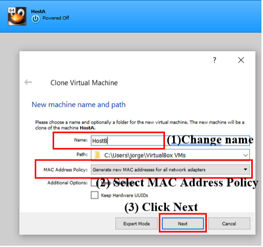
Figure 7: Cloning a virtual machine.
8. Next, choose Full clone and click on the
Clone button, as Figure 8 shows. The cloning process of the virtual machine begins
execution.
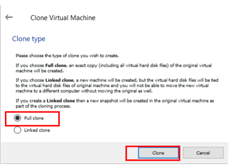
Figure 8: Clone Virtual Machine window.
9. After the cloning process finishes
execution, the cloned virtual machine is ready and can be accessed from the
leftmost side menu below the Tools tab.
5.
Networking Modes
There are many available networking modes to
use to attach the network adapters of a virtual machine. The list of
available networking modes can be seen by expanding the Attached to drop-down
menu under the Network settings of a virtual machine, as Figure
9 shows.
For your virtual environment, you will be working only with the NAT and
internal network modes.
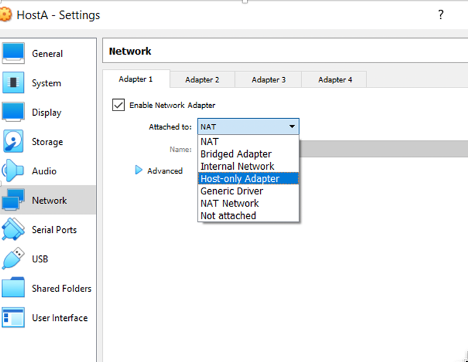
Figure 9: Different networking adapter modes.
NAT networking mode: the
Network address translation (NAT) mode is used to translate a local IP address
assigned to a network adapter in a virtual machine to one of your host network
interface’s IP addresses. This mode is used as a private mode because your
virtual machine can access the internet via your host network interface.
However, external hosts cannot directly access the local network your virtual
machine is attached to.
Internal Network: this
mode is used to configure a private local network (LAN) that does not need
external access (internet), just access (local) within the configured LAN. All
network adapters attached to the same internal network are virtually connected
to the same LAN.
Every virtual machine created from the
provided .ova file provided is equipped with three network adapters, you can
see this in the network settings of your created virtual machine, as Figure
10 shows. The three network adapters are attached as follows:
· Adapter1 is
attached to NAT networking mode (external access)
· Adapter2 is
attached to the internal network, Network1 (local access).
· Adapter3 is
attached to the internal network, Network2 (local access).

Figure 10: Virtual machine's network adapter configuration.
Note: You can create more
internal networks than the two already provided if needed.
6.
Verification of Network Adapters
You can see the configuration of a virtual
machine network adapter by using the diagnostic network tool ifconfig,
as Figure 11 shows.
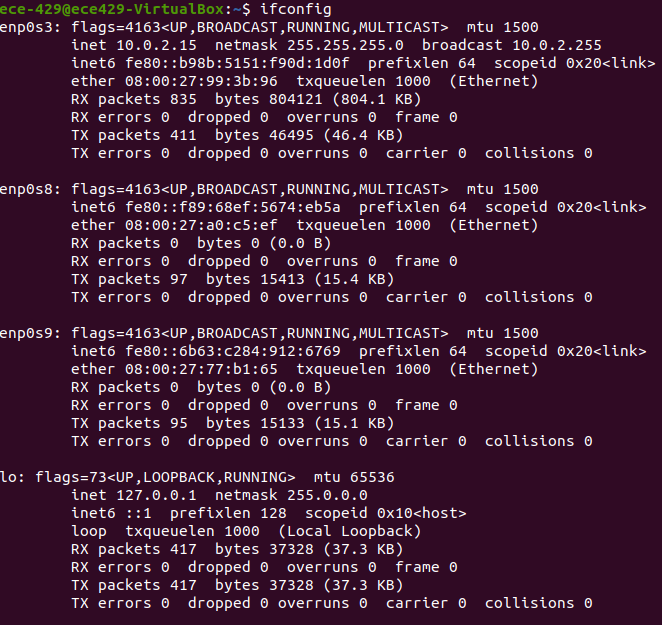
Figure 11: Network adapters’ configuration.
As shown in Figure 11, you can
see that Adapter1 is mapped to interface enp0s3,
Adapter2 to enp0s8, and adapter2 to enp0s9.
Notice also that Adapter1 is assigned a local IP address 10.0.2.15/24 by
VirtualBox by default, while Adapter2 and Adapter3 are not given any. It is
your task to choose and assign a private network address to enable
communications between network adapters attached to the same virtual LAN. You
MUST choose an IP network address different from the already assigned 10.0.2.0/24 network.
Example: Adapter2a 10.0.3.1/24 and Adapter2b
10.0.3.2/24
7.
Internal Network Configuration
You can use the graphical network interface
(GUI) to bring up and assign an IP address to a network adapter. Alternatively,
you could use the command-line interface (terminal) and ifconfig using
the following command:
sudo ifconfig
<replace with interface name> <IP address to be assigned> netmask
<Netmask to be assigned> up
Figure 12 shows an example
where Adapter 2 of both HostA and HostB
are attached to the same internal network (Network1). Adapter1 of both hosts
are by default attached to the NAT networking mode through the host network
adapter to have external access to the internet.
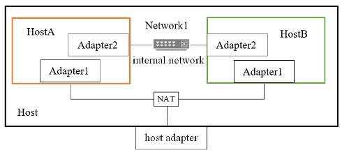
Figure 12: An example of a network setup using NAT and internal
networking modes.