Go to ECE 291 Experiment  1   |   2    |  3   |   4   |  5   |  6   |  7   |  9   |   10   |   11   |    ECE Lab home

ECE291 - LABORATORY VIII

RESONANCE CIRCUITS


OBJECTIVES

Demonstrating resonance phenomena in RLC circuits. Measurements of resonance characteristics and their comparison with theory.


INTRODUCTION

Resonance is one of the most important and general phenomenon in almost all branches of science and technology. For example, in mechanical systems a resonance is often seen in vibrations of a beam or a spring supporting a mass. Vibrations are caused by transfer of the potential energy stored by the beam deflection or the spring contraction to the kinetic energy of the moving mass, back and forth in a periodic motion. In electrical circuits the energy stored in the form of the electric field in a capacitor is transferred to the electric current in the circuit in which inductance plays a role equivalent to the inertial mass in a mechanical system. The equations describing both resonances are identical, only their coefficients have values related to mechanical (mass, spring constant) or electrical (capacitance, inductance) parameters. Another important analogy between the two systems is that the vibrations can be damped; by friction in mechanical systems and by resistance in electrical circuits.

The resonance can be very useful in such devices as oscillators in radio transmitters or electronic watches. More often, however, they can be harmful by generating unwanted wide deflections of mechanical systems (bridges, airplane wings, etc.) or oscillations of voltage and current. Controlling or preventing unwanted resonance is an important aspect of engineering design. Since every electrical component, or even a connecting wire, has some capacitance and inductance there is a potential for resonance in every circuit. As you already know, the smaller the values of inductance and capacitance, the higher the resonance frequency. That is why design of high frequency circuits is so much more difficult as even small inductance and capacitance of connections plays a role. In this set of experiments you will explore resonance in a series RLC circuit, which have the resonance in relatively low and easy to handle frequency range.


Important Relations in Electrical Resonance:

Resonance Frequency

Bandwidth

Quality Factor


PRELAB

Sketch the so called resonance curve for the series resonance circuit in Fig. 7. Put on the vertical axis the current (or voltage across resistor R) and log f on the horizontal axis. Indicate the resonance frequency fo and the width of the resonance curve (the bandwidth), which is the interval Df = 2pG between two frequencies at which the power dissipated in the circuit is ½ of the maximum. Calculate these numbers for specific component values which you may use in the laboratory, for example: R = 1k, C = 1nF, L = 50 mH.

Hint: Note that the three components are connected in series with a voltage source, so it is easy to write an expression for the current (using complex numbers). The current reaches maximum (resonance) for a certain frequency at which the total circuit impedance is equal to R (what is the phase of the current at this frequency?). At half power frequencies the current drops to I/Ö2.

Once you have the expression for current you may well use it in a spreadsheet program (such as MS Excel) or use some other software (such as Matlab) to calculate and plot the resonance curve (ratio VR/VS as a function of log f). You will need it also for your report. Alternatively, you may simulate the circuit operation with PSPICE.


LABORATORY

Equipment needed from the stockroom: parts kit, proto-board, leads, scope probes.

1.     SERIES RESONANCE CIRCUIT DRIVEN BY A SINUSOIDAL VOLTAGE

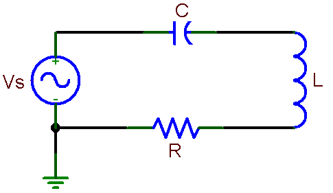
a)    Assemble the series resonance circuit shown below. Use 50 mH coil from your parts kit for L, select a resistor, no more than 1 k ohm, and a capacitor of 1 to a few nF. Measure the values of these components before assembly. Measure also the coil resistance with the digital ohmmeter. Calculate the expected resonance frequency.

Fig. 7 Series resonance circuit


b)     Attach one scope probe across the voltage source, the other across R and observe the two signals on different scope channels simultaneously. Note amplitudes and phase difference while changing the frequency. If the voltage amplitude of the generator vary with frequency, you may adjust it to keep it constant, otherwise note its values for different frequencies. Obtain sufficient number of data points for plotting of the resonance curve. Try to determine precisely the resonance frequency at the peak of the curve and the frequencies at the half power points on both sides of the maximum. Measure also the phase shift between VS and VR at these three frequencies and a few other frequencies on both sides of the maximum. It is usually easier to find precisely the resonance frequency from the phase measurement than from the amplitude. Find frequencies where the phase difference is 0, + 45o, and – 45o.

c)     Measure also the voltage across the capacitor at the resonance by using the signal subtraction function of the digital oscilloscope. Note that it is larger than the generator voltage. The ratio of these voltage value is equal to the Q value of the circuit.

2.   RESONANCE CIRCUIT EXCITED WITH A STEP VOLTAGE

Switch the waveform generator from a sine wave to a square wave at the resonance frequency of the circuit. What is the shape of the current waveform? Can you explain this observation?

Next, adjust the square wave frequency to about one tenth of the circuit resonance frequency. Expand the image horizontally and observe the signal shape after the step of the input signal. Determine the frequency of the oscillations after each step. The image shows a response of any resonance system to an external disturbance represented here by a pulse (square wave). Print the scope image.

3.   CIRCUIT SIMULATION (at home).

Simulate measurements 1 and 2: frequency response of amplitude and phase and the time dependence of current with a square wave input. Use the same values of R, L, and C in simulations as in the laboratory. Compare results of simulations with measurements.

REPORT

  • Make graphs of the resonance curves showing the amplitude (plot VR/VS) and the phase (ÐVR - ÐVS) as functions of frequency.


  • Compare the measured values of the resonance frequency and the widths of the resonance curves at half power maximum (the bandwidth) with the values calculated from the known circuits components.


  • How does the phase change across the resonance curve?


  • The best way to present and discuss the results is to make a graph of the resonance curve showing the experimental points as well as the theoretical curve calculated from a spreadsheet (see Prelab). Use a large number of calculated frequencies to obtain a smooth curve.


  • Compare results of 1 c) with calculated Q and the G obtained from the frequency distribution in 1 b).


  Go to ECE 291 Experiment  1   |   2    |  3   |   4   |  5   |  6   |  7   |  9   |   10   |   11   |    ECE Lab home