|
|
Go to ECE459 Experiment | 1 | 2 | 3 | 4 | Lab manuals | ECE Lab home |
|
|
|
Go to ECE459 Experiment | 1 | 2 | 3 | 4 | Lab manuals | ECE Lab home |
|
ECE459 Advanced Computer System Design Lab
Chapter 2
Experiment 2
Systolic-Array Implementation of Matrix-By-Matrix Multiplication
2.1 Objective
n x n matrices. For this reason, several parallel algorithms have been developed to solve this problem more efficiently. Here, a simple parallel algorithm is presented for this problem and a "hardwired" (actually, systolic-array) implementation of the algorithm becomes our objective.The multiplication of matrices is a very common operation in engineering and scientific problems. The sequential implementation of this operation is very time consuming for large matrices; the brute-force solution results in computation time O(n3), for
2.2 Introduction
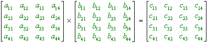
2-dimensional, mesh-connected parallel computers are often used in systolic-array configuration for the multiplication of matrices. For the sake of simplicity, we assume input matrices of size 4 x 4 containing one-bit integer elements. Figure 2.1 shows the operations to be performed. The ● and + represent the integer operations multiplication and addition, respectively.
|
c11
= a11 ● b11
+ a12 ● b21
+ a13 ● b31
+ a14 ● b41
|
|
Figure 2.1: Multiplication of matrices of size 4 4. |
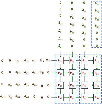
A and B are shifted into the boundary processors in column 1 and row 1, respectively, as shown in Figure 2.2. The leading and trailing 0s in rows and columns are employed so that elements air and brj arrive at processor Pij simultaneously for the operation air ● brj to be performed. cij is initialized to 0 in Pij , for all i, j = 1, 2, 3, 4. At the end, processor Pij will contain cij , for 1 ≤ i, j ≤ 4
The two matrices
Whenever a processor
Pij receives two inputs b and a from the north and the west, respectively, it performs the following set of operations, in this order:it calculates
it adds the result to the previous value
it sends
it sends
This algorithm takes time O(n), for n x n matrices.
|
|
|
Figure 2.2: A 4 x 4 mesh (systolic array) of processors for matrix multiplication. |
2.4 Experiment
Implement this parallel algorithm directly in hardware using the Altera UP 1 Education Board. Optimize your design with respect to the size of operands. Use onboard LEDs and/ or BCD displays to display intermediate and final results.
The proper operation of the entire design is to be simulated in MAX+PLUS before UP 1 is programmed. The waveforms from these simulations should be included in the lab report.
|
|
Go to ECE459 Experiment | 1 | 2 | 3 | 4 | Lab manuals | ECE Lab home |
|