|
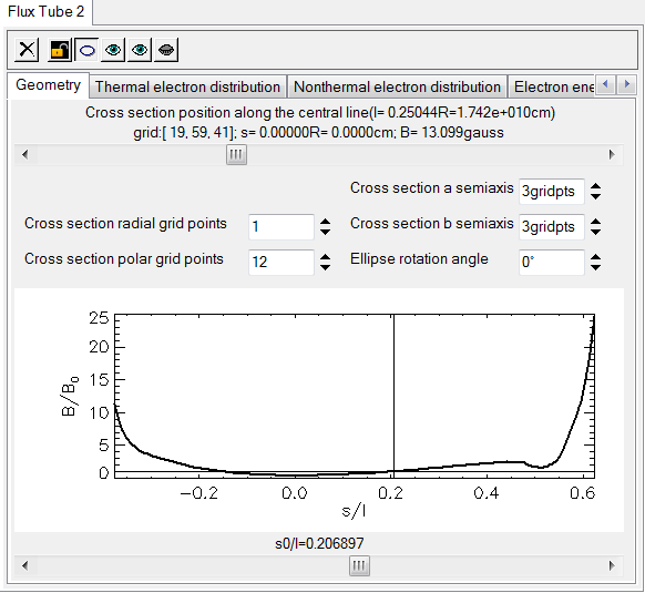
The Geometry page of a flux tube property displays its geometrical properties and presents the controls needed to modify these properties. The appearance of this page depends on the circular or elliptical shape of the cross section selected by the user by toggling the shape button located on the toolbar menu.
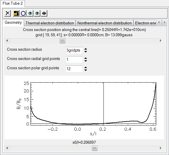
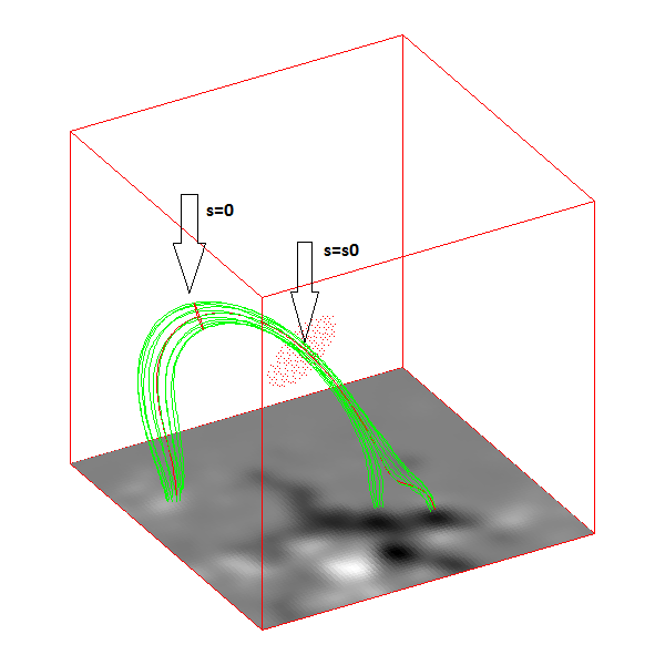
This slider controls the position of the flux tube defining cross section along the central field line, which may vary between the two end points of the central field line in discreet steps determined by the individual positions of the points belonging to it, as described in the section How to Create Magnetic Field Lines . The initial position of the flux tube cross section correspond to the s=0 field line coordinate, which corresponds to the point of minimum of the magnetic field strength along the field line. By changing this default position, the appearance of the flux tube is changed due to the fact that the flux tube boundary lines are recomputed such as to originate in the grid points of the cross section surface.
Along with the s coordinate corresponding to the selected cross section, the length of the central field line, magnetic field strength, and data cube voxel location of the surface position are also displayed.
This input field, available if the circular cross section shape is selected in the flux tube toolbar menu , controls the radius of the cross section in units of data cube grid points. The default value is 1 grid point, but larger values may be considered to produce larger cross sections.
These input fields, available if the elliptical cross section shape is selected in the flux tube toolbar menu, control the semiaxes of the cross section ellipse in units of data cube grid points. When switching from circular to elliptical shape, both fields are set equal to the same value as the circular cross section radius. When switching from elliptical to circular cross section, the radius is set to the current value of the a semiaxis.
To mitigate the unique ownership of a voxel volume between more than one flux tube and between the existent flux tubes and corona, GX_Simulator always takes in consideration the voxels situated within a 3R or 3a distance from the central line of a given flux tube. Therefore, the flux tube voxel ownership may actually extend up to a distance of 3R or 3a, beyond the visible field lines that intersects a given cross section. The true boundary of a given flux tube may be visualized by opening the Volume View eye located on the Volume View toolbar .
For this reason, it is recommended to open the Volume View eye immediately after the first flux tube is added to the model.
These two parameters determine how many field lines interseting the cross section, one for each polar grid of the cross section surface, are computed for display purposes. The default settings results in displaying only a set of cross-section boundary field lines.
This plot displays the magnetic field strength variation along the central field line relative to a reference value B0, which is measurred in a reference point of the central field line having the coordinate s0 relative to the point of minimum magnetic field line along the central field line. The abscissa of this plot represents the central field line corordinate, s, measured from the point of minimum magnetic field (s=0) normalized by the length of the central field line, l .
This slider sets the position of the reference point, s0, chosen by the user along the central field line. Based on this selection, the reference magnetic field strength is used, and the B/B0 profile is computed. In addition, in the Volume View display, a cloud of red points, laying on a circular normal surface of radius R (or a ) that crosses the central field line at s=s0, indicates the distance relative to the central field line at which the magnetic flux tube may influence the structure of the data cube model.