ECE291 - LABORATORY IV INTERNAL IMPEDANCE OF INSTRUMENTS; INFLUENCE OF INSTRUMENTS ON CIRCUITS
OBJECTIVES Demonstrating the difference between "ideal" and real instruments and the influence of real instruments on circuits. Measurements of internal resistances of digital and analog voltmeters, ammeters, and the output resistance of a voltage source (a waveform generator).
INTRODUCTION In the previous experiments we built circuits and made measurements on them by attaching instruments (a voltmeter, an ammeter or a scope) to various circuit points. In analyzing circuits performance we neglected the instruments presence assuming tacitly that they have no influence on current and voltage distributions. Such an assumption is valid only for "ideal" instruments but may be quite reasonable also for real instruments in most practical cases. There are situations, however, where the presence of an instrument attached to a circuit alters its performance to the point where the measurement is meaningless, and other methods of circuit evaluation are needed. For instance, if a voltmeter connected across a circuit element draws a current comparable to the current flowing through that element, it changes the current and voltage distribution in the rest of the circuit. An ideal voltmeter does not draw any current, a good voltmeter very little. Modern digital voltmeters are very good in this respect. A real instrument, such as a digital or analog voltmeter, may be represented by an equivalent circuit consisting of an ideal meter and its internal resistance. In general we should consider internal impedance, which beside resistance may have a capacitive or inductive component. For example, a capacitive component of the scope input impedance plays a role in high frequency measurements. We will see this effect in the next laboratory. Another class of instruments in which internal resistance plays an important role is represented by power supplies. A voltage supply, such as a battery or the power supply at your bench can be represented as an ideal voltage source and a resistance (output resistance). In an ideal voltage source this resistance is zero, so there is no voltage drop across it, and the output voltage is independent of the amount of the current drawn. In this set of experiments you will measure internal resistance of basic instruments used in the laboratory and demonstrate simple situations where their internal resistance plays an important role. The lesson is worth remembering whenever you attach external instruments to an electronic circuit. We will revisit the topic of the input impedance of our most important instrument, the oscilloscope, in a later laboratory. The complex impedance of the oscilloscope requires knowledge of the response of RC circuits, which will be covered first.
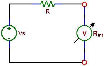
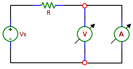
PRELAB 1. Knowing that to measure voltage you need to connect a voltmeter between two points of a circuit and that the voltmeter should have little effect on the circuit, what do you think is the value of the voltmeter internal resistance, high or low? What is the resistance of an ideal voltmeter which does not influence a circuit at all (does not draw any current)? A real voltmeter can be represented by a circuit consisting of an ideal voltmeter and a resistor representing its internal resistance. Draw the schematic of that circuit, indicating terminals which represent leads used for voltage measurements. Write an equation for finding the unknown voltmeter internal resistance Rint if you know the value of the resistor R and the voltage Vs in experiment 1.1 of this laboratory( Fig 4.1). 2. Draw an equivalent circuit of a real ammeter, consisting of an ideal instrument and the internal resistance. Again, a good instrument should have a minimal effect on a circuit being measured. Remember that, unlike a voltmeter, an ammeter connects in series with the measured circuit. So, an ideal ammeter should not resist current flow and should not develop any voltage across its terminals. 3. An ideal voltage source gives voltage which is independent of current. A real source can be represented by an ideal source and the internal resistance, on which a voltage drop develops as the current flows. Thus a real voltage source gives lower voltage with a load (e.g. a resistor) than without a load. Write an equation for finding the unknown waveform generator internal resistance Rint if you know the value of the load resistor RL and the voltages measured in experiment 1.3 of this laboratory
|


