|
ECE 291 - LABORATORY IX
THE DIODE AND DIODE CIRCUITS
OBJECTIVES
To measure characteristics of a rectifier and a Zener diodes and
to understand the difference between an
"ideal diode" and a real device. To familiarize students with basic rectifiers and other diode circuits.
PRELAB
1.
What are the differences between characteristics of a model
"ideal diode" and a real device?
2.
What is the difference between a Zener diode and a
"standard" rectifier diode?
3.
Draw a "load line" plot for a circuit with a
d.c.
source, forward biased diode and a resistor.
The plot should have the diode voltage on the horizontal axis and current on the vertical axis. Mark both scales with numerical
values in volts and mA, respectively. Draw
two straight load lines representing two resistors with specific values
(between 1 and 10 kohms). Draw a reasonable "diode characteristic"
curve on the same graph; you will measure it
later in the lab. Mark two operating points corresponding
to the two resistors.
References: T. C. Hayes and P. Horowitz "Student Manual for
The Art of Electronics" pp. 65-77.
Cambridge University Press 1989.
Also in P. Horowitz and W. Hill
"The Art of Electronics" 2-nd ed.
LABORATORY
Equipment needed from the stockroom:
Parts
kit, proto-board, analog universal meter, resistance
substitution box, leads.
1. MEASUREMENTS OF I-V CHARACTERISTICS OF A RECTIFIER DIODE.
a)
Measure the I-V characteristic of a rectifier diode or the
dependence of current through the diode on
voltage across the diode. For measurements with forward diode bias
you need a voltmeter and an ammeter; use the analog and the digital meters. An incandescent lamp in series with the diode makes a
handy "high power" resistor. Do not
burn the bulb (stop increasing current when it becomes bright)! Cover a wide range of current values, from a fraction of a mA to
about 100mA. Plot the current as a function
of the bias voltage. Make a preliminary graph in the laboratory.
b)
Apply a reverse bias to the diode of a few volts to see how
large the reverse current is. Even your
digital ammeter may not be able to measure a very small reverse current. Can
you determine it by measuring voltage across a high value resistor (MW) connected in series with the diode? Think which of
the two voltmeters to use in this measurement
(consider their internal resistances!).
2. ZENER DIODE
Measure the I-V characteristic of a Zener diode with reverse
bias. Use an appropriate series resistor
(the light bulb may do it) to permit a few tens of mA of current after achieving
a breakdown voltage. Make a preliminary graph in the laboratory.
Plot reverse bias characteristic of the Zener diode and
determine the Zener breakdown voltage.
3. A DIODE IN A CIRCUIT; THE LOAD LINE
a)
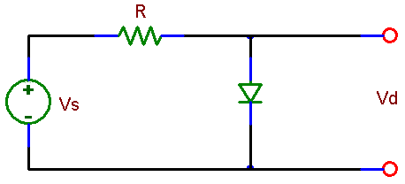
Assemble the circuit shown below using the rectifier diode
which characteristic you measured in 1.
Choose the resistor of about 2 kohm. Measure the voltage across it while
increasing slowly the power supply voltage to obtain current of a few mA.
Make sure that the current is in
the range you covered in the measurement of the diode characteristic
in section 1. Measure also the voltage across the circuit (Vs)
and across the diode.
|

|
|
Fig.
8.1
A diode in a circuit with a resistor
|
|


