Go to EE395 Experiment 1 2 3 4 5 Microprocessor board 8251A Interface SBC EEPROM ECE Lab home
![]()
|
Go to EE395 Experiment 1 2 3 4 5 Microprocessor board 8251A Interface SBC EEPROM ECE Lab home |
|
EE395 - Microprocessor Laboratory
Computer Construction Project and Experiments
Experiment 5 - DAC Interface with the SBC
Objectives
This experiment is used to familiarize students with interfacing computers to the analog world. This is necessary because in the real world there are multitudes of analog devices which need to be interfaced to digital equipment. To interface computers and digital devices to the analog world we commonly use A/D (analog to digital) and D/A (digital to analog) converters. The A/D converter takes an analog signal and converts it to a digital value. The output is the ratio of the input voltage to the reference voltage of the A/D converter. The D/A converter does the opposite. It takes the digital value and generates an analog voltage which is proportional to a reference voltage.

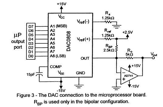
Ina this experiment a DAC0808 8-bit digital to analog converter is interfaced to the microprocessor parallel I/O output port as shown in figure 3. This setup will then be used for the generation square, sine and triangular waveforms.
The D/A converter used in this experiment is the DAC0808 available from the National Semiconductor. The specification sheets can be obtained from the National Semiconductor Linear Data Book available in the stockroom.
Prelab Assignments
1. Prepare commented assembly language programs to generate the waveforms in the following section. Prepare flow charts for these programs. Do not replicate common portions of the code or flow charts.
2. Compute the current flow out of the DAC of
figure 3 when it sees the following data bytes:
(a) 30H
(b) 0A1H
(c) 0FAH
Assume that the reference voltage Vref = 5.0 V and that Rref = 5 KW.
Lab assignments
Connect the DAC and associated components to the output port of the microprocessor. Write programs to output a binary sequence so as to generate:
1. A Square Wave (both unipolar and bipolar)
2. A Sawtooth Wave (both unipolar and bipolar)
3. A Sine Wave (bipolar only)
The waves should be periodic, with a period controllable by a scale stored in a specific RAM address. Select a reasonable range of frequencies, taking into account the dynamic properties of the DAC and of your microcomputer. Display the output waveforms on an oscilloscope.