Go to ECE489 Experiment | 1 | 2 | 3 | 4 | 5 | 6 | 7 | 8 | 9 | 10 | 11 | 13 | 14 | ECE Lab home
![]()
|
|
Go to ECE489 Experiment | 1 | 2 | 3 | 4 | 5 | 6 | 7 | 8 | 9 | 10 | 11 | 13 | 14 | ECE Lab home |
|
ECE 489 Communications Systems Laboratory
Experiment 12 : ASK - AMPLITUDE SHIFT KEYING
ACHIEVEMENTS: Generation and demodulation of an amplitude shift keyed (ASK) signal.
PREREQUISITES: It would be advantageous to have completed some of the experiments in Volume A1 involving linear modulation and demodulation.
EXTRA MODULES: DECISION MAKER
Amplitude shift keying -ASK -in the context of digital communications is a modulation process which imparts to a sinusoid two or more discrete amplitude levels* (Also called on-off keying - OOK). These are related to the number of levels adopted by the digital message.
For a binary message sequence there are two levels, one of which is typically zero. Thus the modulated waveform consists of bursts of a sinusoid.
Figure 1 illustrates a binary ASK signal (lower), together with the binary sequence which initiated it (upper). Neither signal has been bandlimited.
 |
| Figure 1: An ASK signal (below) and the message (above) |
There are sharp discontinuities shown at the transition points. These result in the signal having an unnecessarily wide bandwidth. Bandlimiting is generally introduced before transmission, in which case these discontinuities would be 'rounded off' . The bandlimiting may be applied to the digital message, or the modulated signal itself.
The data rate is often made a sub-multiple of the carrier frequency. This has been done in the waveform of Figure 1.
One of the disadvantages of ASK, compared with FSK and PSK, for example, is that it has not got a constant envelope. This makes its processing (eg, power amplification) more difficult, since linearity becomes an important factor. However, it does make for ease of demodulation with an envelope detector.
A block diagram of a basic ASK generator is shown in Figure 2. This shows bandlimiting following modulation.
 |
| Figure 2: the principle of ASK generation |
The switch is opened and closed by the unipolar binary sequence
As already indicated, the sharp discontinuities in the ASK waveform of Figure 1 imply a wide bandwidth. A significant reduction can be accepted before errors at the receiver increase unacceptably. This can be brought about by bandlimiting (pulse shaping) the message before modulation, or bandlimiting the ASK signal itself after generation.
Both these options are illustrated in Figure 3, which shows one of the generators you will be modeling in this experiment.
|
|
|
Figure 3: ASK bandlimiting, with a LPF or a BPF . |
Figure 4 shows the signals present in a model of Figure 3, where the message has been bandlimited. The shape, after bandlimiting, depends naturally enough upon the amplitude and phase characteristics of the bandlimiting filter.
 |
| Figure 4: original TTL message (lower), bandlimited message (center), and ASK (above) |
You can approximate these waveforms with a SEQUENCE GENERATOR clocked at about 2 kHz, filter #3 of the BASEBAND CHANNEL FILTERS, and a 10 kHz carrier from a VCO.
It is apparent from Figures 1 and 4 that the ASK signal has a well defined envelope. Thus it is amenable to demodulation by an envelope detector.
A synchronous demodulator would also be appropriate.
Note that:
Envelope detection circuitry is simple.
Synchronous demodulation requires a phase-Iocked local carrier and therefore carrier acquisition circuitry .
With band limiting of the transmitted ASK neither of these demodulation methods would recover the original binary sequence; instead, their outputs would be a band limited version. Thus further processing - by some sort of decision-making circuitry for example - would be necessary.
Thus demodulation is a two-stage process:
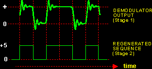
Recovery of the bandlimited bit stream
Regeneration of the binary bit stream
Figure 5 illustrates.
 |
| Figure 5: The two stages of the demodulation process |
It is easy to estimate the bandwidth of an ASK signal. Refer to the block diagram of Figure 3. This is a DSB transmitter. It is an example of linear modulation. If we know the message bandwidth, then the ASK bandwidth is twice this, centered on the 'carrier' frequency.
Using the analogy of the DSB generator, the binary sequence is the message (bit rate 'm'), and the sinewave being switched is the carrier ('w').
Even though you may not have an analytical expression for the bandwidth of a pseudo random binary sequence, you can estimate that it will be of the same order as that of a square, or perhaps a rectangular, wave.
For the special case of a binary sequence of alternate ones and zeros the spectrum will:
Be symmetrical about the frequency of the carrier 'w'
Have a component at 'w', because there will be a DC term in the message
Have sidebands spaced at odd multiples of 'm' either side of the carrier
Have sideband amplitudes which will decrease either side of the carrier (proportional to 1/n, where 'n' is the order of the term).
If you accept the spectrum is symmetrical around the carrier then you can measure its effective bandwidth by passing it through a tunable lowpass filter. A method is suggested in the experiment below.
You can discuss this when answering Tutorial Question Q2.
There are many methods of modeling an ASK generator with TIMS. For any of them the binary message sequence is best obtained from a SEQUENCE GENERATOR, clocked at an appropriate speed. Depending upon the generator configuration, either the data bit stream can be bandlimited, or the ASK itself can be bandpass filtered.
Suggestions for modeling the ASK generators are:
T1.1 modeling with a DUAL ANALOG SWITCH
It is possible to model the rather basic generator shown in Figure 2.
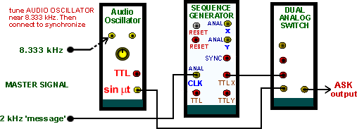
The switch can be modeled by one half of a DUAL ANALOG SWITCH module. Being an analog switch, the carrier frequency would need to be in the audio range. For example, 15 kHz from a VCO. The TTL output from the SEQUENCE GENERATOR is connected directly to the CONTROL input of the DUAL ANALOG SWITCH. For a synchronous carrier and message use the 8.333 kHz TTL sample clock (filtered by a TUNABLE LPF) and the 2.083 kHz sinusoidal message from the MASTER SIGNALS module.
If you need the TUNABLE LPF for bandlimiting of the ASK, use the sinusoidal output from an AUDIO OSCILLATOR as the carrier. For a synchronized message as above, tune the oscillator close to 8.333 kHz, and lock it there with the sample clock connected to its SYNCH input.
This arrangement is shown modeled in Figure 6.
 |
| Figure 6: Modeling ASK with the arrangement of Figure 2 |
Bandlimiting can be implemented with a filter at the output of the ANALOG SWITCH.
T1.2 Modeling with a MULTIPLIER
A MULTIPLIER module can be used as the switch. The carrier can come from any suitable sinusoidal source. It could be at any available TIMS frequency.
The other input to the MULTIPLIER needs to be the message sequence.
Neither the TTL nor the analog sequence is at an appropriate voltage level. Each requires amplitude scaling. This can be implemented in an ADDER, which will invert the sequence polarity. DC from the VARIABLE DC module can be used to re-set the DC level. The required signal will be at a level of either O V or +2 V, the latter being optimum for the (analog) MULTIPLIER.
This arrangement is shown modeled in Figure 7.
Figure 7: modeling ASK with the arrangement of Figure 3
The operating frequency of the modulator of Figure 7 is not restricted to audio frequencies. Any carrier frequency available within TIMS may be used, but remember to keep the data rate below that of the carrier frequency.
For a synchronous system (i.e., message and carrier rates related, so as to give 'stable' oscilloscope displays):
Clock the SEQUENCE GENERATOR from the 2 kHz message (as shown), or the 8.333 kHz sample clock.
Use a 100 kHz carrier (as shown), or an AUDIO OSCILLATOR locked to the 8.333 kHz sample clock.
Any other combination of data clock and carrier frequency, synchronous or otherwise, is possible (with this model); but not all combinations will generate an ASK signal. Try it !
Bandlimiting can be implemented with a filter at the MULTIPLIER output (a 100 kHz CHANNEL FILTERS module), or the bit sequence itself can be bandlimited (BASEBAND CHANNEL FILTERS module).
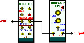
Having generated an ASK signal, an estimate of its bandwidth can be made using an arrangement such as illustrated in Figure 8. The bandwidth of the lowpass filter is reduced until you consider that the envelope can no longer be identified.
This will indicate the upper frequency limit of the signal. Do you think it reasonable to then make a declaration regarding the lower frequency limit ?
 |
| Figure 8: ASK bandwidth estimation |
The arrangement of Figure 8 is easy to model with TIMS. Use the TUNABLE LPF. But remember to select appropriate ASK frequencies.
Both asynchronous and synchronous demodulation methods are used for the demodulation of ASK signals.
Having a very definite envelope, an envelope detector can be used as the first step in recovering the original sequence. Further processing can be employed to regenerate the true binary waveform.
Figure 9 is a model for envelope recovery from a baseband FSK signal.
 |
| Figure 9: envelope demodulation of baseband ASK |
If you choose to evaluate the model of Figure 9, remember there is a relationship between bit rate and the lowpass filter bandwidth. Select your frequencies wisely.
A synchronous demodulator can be used for demodulation, as shown in Figure 10, In the laboratory you can use a stolen carrier, as shown.
 |
| Figure 10: synchronous demodulation of ASK |
T3.3 Post-demodulation processing
The output from both of the above demodulators will not be a copy of the binary sequence TTL waveform. Bandlimiting will have shaped it, as (for example) illustrated in Figure 4.
Some sort of decision device is then required to regenerate the original binary sequence. The DECISION MAKER module could be employed, with associated processing, if required. This is illustrated in block diagram form in Figure 11.
 |
| Figure 11 |
This model will regenerate a bi-polar sequence from the recovered envelope.
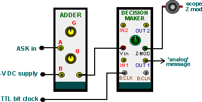
Figure 12 shows the model of the block diagram of Figure 11
 |
| Figure 12: regeneration to a bi-polar sequence |
Remember to
Convert the uni-polar, bandlimited output of the envelope detector to bi-polar (using the ADDER), to suit the DECISION MAKER.
Set the on-board switch SW1, of the DECISION MAKER, to NRZ-L. This configures it to accept bi-polar inputs.
Adjust the decision point of the DECISION MAKER
In the first instance, use a stolen carrier and bit clock
The output will be the regenerated message waveform. Coming from a YELLOW analog output socket, it is bi-polar ±2 V (not TTL).
The same regenerator can be used to process the output from the synchronous demodulator of Figure 10.
Rather than using a stolen carrier and bit clock you might like to try recovering these from the received ASK signal.
Q1 Suggest an advantage of making the data rate a sub-multiple of the carrier rate.
Q2
Discuss your methods of measuring and/or estimating the bandwidth of the ASK signal. Estimate the maximum amount of bandwidth limiting possible, and the trade-offs involved.
Q3
The ASK waveform of Figure 1 is
'special' in that.
The bit rate is a sub-multiple of the carrier
The phasing of the message ensures that each 'burst' of carrier starts and ends at zero amplitude.
If these special conditions are changed, consider the shape of the waveform at the beginning and end of each burst of carrier. What effect, if any, will this have on the bandwidth of the ASK signal ?
|
|
Go to ECE489 Experiment | 1 | 2 | 3 | 4 | 5 | 6 | 7 | 8 | 9 | 10 | 11 | 13 | 14 | ECE Lab home |
|