Go to ECE489 Experiment | 1 | 2 | 3 | 4 | 5 | 6 | 7 | 8 | 9 | 10 | 11 | 12 | 13 | 14 | ECE Lab home
![]()
| |
Go to ECE489 Experiment | 1 | 2 | 3 | 4 | 5 | 6 | 7 | 8 | 9 | 10 | 11 | 12 | 13 | 14 | ECE Lab home |
|
ECE 489 Communications Systems Laboratory
Experiment 6: Envelopes
ACHIEVEMENTS: Definition and examination of envelopes; the envelope of a wideband signal, although difficult to visualize , is shown to fit the definition
PREREQUISITES: completion of the experiments entitled DSBSC generation, and AM generation, in this volume, would be an advantage.
When we talk of the envelopes of signals we are concerned with the appearance of signals in the time domain. Text books are full of drawings of modulated signals, and you already have an idea of what the term 'envelope' means. It will now be given a more formal definition.
Qualitatively, the envelope of a signal y( t ) is that boundary within which the signal is contained, when viewed in the time domain. It is an imaginary line.
This boundary has an upper and lower part. You will see these are mirror images of each other. In practice, when speaking of the envelope, it is customary to consider only one of them as 'the envelope' (typically the upper boundary).
Although the envelope is imaginary in the sense described above, it is possible to generate, from y( t ), a signal e(t), having the same shape as this imaginary line. The circuit which does this is commonly called an envelope detector. See the experiment entitled Envelope recovery in this Volume.
For the purposes of this discussion a narrowband signal will be defined as one which has a bandwidth very much less than an octave. That is, if it lies within the frequency range f1 to f2, where f1 < f2, then:
log2 ( f1 / f2) << 1
Another way of expressing this is to say that f1 » f2 so that
( f1 - f2) / ( f1 + f2) << 1
A wideband signal will be defined as one which is very much wider than a narrowband signal !
For further discussion see the chapter, in this Volume, entitled Introduction to modeling with TlMS, under the heading bandwidth and spectra.
Every signal has an envelope, although, with wideband signals, it is not always conceptually easy to visualize. To avoid such visualization difficulties the discussion below will assume we are dealing with narrow, band signals. But in fact there need be no such restriction on the definition. as will be seen later.
Suppose the spectrum of the signal y( t ) is located near fo Hz, where:
|
wo = 2pfo |
( 1 ) |
We state here, without explanation, that if y( t ) can be written in the form
|
y( t ) = a(t) · cos [wot + j (t) ] |
( 2 ) |
where a (t) and j (t) contain only frequency components much lower than fo , (i.e.., at message, or related, frequencies), then we define the envelope e ( t ) of y( t ) as the absolute value of a( t ).
That is,
|
envelope e(t) = | a(t) | |
( 3 ) |
Remember that an AM signal has been defined as:
| y( t ) = A·(1 + m·cosmt)·coswt |
( 4 ) |
where m, w, and m, have their usual meanings.
It is common practice to think of the message as being m·cosmt. Strictly the message should include the DC component; that is (1 + m·cosmt). But the presence of the DC component is often forgotten or ignored.
Example 1: 100% AM
Consider first the case when y(t) is an AM signal.
From the definitions above we see:
a(t) = A·(1 + m·cosmt)( 5 )
j (t) = 0
( 6 )
The requirement that both a( t ) and j (t) contain only components at or near the message frequency are met, and so it follows that the envelope must be e(t), where:
e(t ) = | A·(1 + m·cosmt) | ( 7 )
For the case m Ł 1 the absolute sign has no effect, and so there is a linear relationship between the message and envelope, as desired for AM.
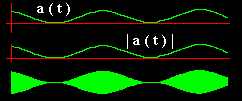 |
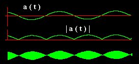
| Figure 1: AM, with m = 1 |
This is clearly shown in Figure I, which is for 100% AM (m = 1). Both a(t) and its modulus is shown. They are the same.
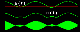
Example 2: 150% AMFor the case of 150% AM the envelope is still given by e(t) of eq. 7, but this time m = 1.5, and the absolute sign does have an effect.
 |
|
Figure 2: 150% AM |
Figure 2 shows the case for m = 1.5. As well as the message (upper trace) the absolute value of the message is also plotted (center trace). Notice how it matches the envelope of the modulated signal (lower trace).
Example 3: DSBSCFor a final example look at the DSBSC, where a(t) = cosmt. There is no DC component here at all. Figure 3 shows the relevant waveforms.
 |
| Figure 3: DSBSC |
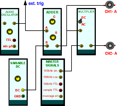
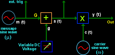
The validity of the envelope definition can be tested experimentally. The arrangement of Figure 4 will serve to make some envelopes for testing. It has already been used for AM generation in the earlier experiment Envelope Modulation -method 1.
Note: in this experiment you will be observing envelopes. but not recovering them. The recovery of envelopes is the subject of the experiment entitled Envelope recovery within this Volume.
 |
|
Figure 4: a test signal generator |
T1 Patch up the model of Figure 4, to generate 100% AM, with the frequency of the AUDIO OSCILLATOR about 1 kHz, and the high frequency term at 100 kHz coming from the MASTER SIGNALS module.
T2
Make
sure that the oscilloscope display is stable, being triggered from the message generator. Display
a(t)
- the message including the DC component- on the oscilloscope channel (CH
1-A), and y(t), the output signal, on channel (CH2-A). Your patching arrangements are shown in
Figure 5 below.
|
|
|
Figure 5: The generator modeled by TIMS |
Example 1The case m Ł 100% requires the message to have a DC component larger than the AC component. The signal is illustrated in Figure 1 for m = 1.
T3 Confirm that, for the case m .$. 1 the value of
e( t )
is the same as that of a(
t ), and so the envelope has the same
shape as the message.
Example 2The case m > 100% requires the message to have a DC component smaller than the AC component. The signal is illustrated in Figure 2.
T4 Set m = 1.5 and reproduce the traces of Figure 2.
Example 3
DSBSC has no carrier component, so the DC part of the message is zero. The signal is illustrated in Figure 3.
T5 Remove the DC term from the ADDER; this makes the output signal a DSBSC. Confirm that the analysis gives the envelope shape as I cosmt I and that this is displayed on the oscilloscope.
In the experiment entitled Envelope recovery you will examine ways of generating signals, which are exact copies of these envelopes. from the modulated signals themselves.
Envelope Visualization for small (w / m)
It has already been confirmed, in all cases so far examined, that there is agreement between the definition of the envelope, and what the oscilloscope displays. The conditions have been such that the carrier frequency was always considerably larger then the message frequency -that is, w >> m. In discussions on envelopes this condition is usually assumed; but is it really necessary?
For some more insight we will examine the situation as the ratio (w / m) is reduced, so that the relation w >> m is no longer satisfied. To do this you will discard the 100 kHz carrier, and use instead a variable source from the VCO.
As a first check, the VCO will be set to the 100 kHz range, and an AM signal generated, to confirm the performance of the new model.
For all displays to follow, remember to keep the message waveform (CH1-A) so it just touches the AM waveform (CH2-A), thus clearly showing the relationship between the shape of a(t) and e(t).
T6 Before plugging in the VCO set it into 'VCO mode' with the switch located on the circuit board. Select the HI frequency range with the front panel toggle switch. Plug it in, and set the frequency to approximately 100 kHz
T7
Set the message frequency from the AUDIO OSCILLATOR to, say, 1 kHz.
T8
Remove the patch cord from the 100 kHz sine wave of the MASTER SIGNALS
module, and connect it to the analog output of the
VCO.
T9
Confirm that the new model can generate AM and then adjust the depth of modulation to somewhere between say
50% and 100%,
A clear indication of what we call the envelope will be needed; since this is AM, with m < 1, this can be provided by the message itself. Do this by shifting the message, displayed on CH1-A, down to be coincident with the envelope of the signal on CH2-A. Now prepare for some interesting observations.
T10 Slowly vary the
VCO
frequency over its whole
HI range. Most of the time the display will be similar to that
of figure 1 but it might be possible to obtain momentary
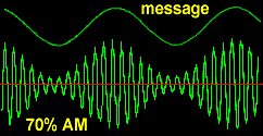
glimpses of the AM signal as it appears in Figure 6.
If you obtain a momentary display, such as shown in Figure 6, notice how the AM signal slowly drifts left or right, but always fits within the same boundary, the top half of which has been simulated by the message on the other trace.
Figure 6: single sweep of a 70% AM
Reduction of the carrier-to-message freq ratio
The ratio of carrier-to-message frequency so far has been about 100: 1.
The mathematical definition of the envelope puts no restraint on the relative size of w and m, except, perhaps, to say that w ł m.
Can you imagine what would happen to the envelope if this ratio could be reduced even further ?
To approach this situation, as gently as possible:
T11 Rotate the frequency control of the VCO fully clockwise. Change the frequency range to LO, with the front panel toggle switch.
The AM signal will probably still look like that of Figure 1. But now slowly decrease the carrier frequency (the VCO), repeating the steps previously taken when the carrier was 100 kHz.
T12 Slowly reduce the VCO frequency, and thus the ratio (w
/ m). Monitor the VCO
frequency with the FREQUENCY COUNTER, and keep a mental note of the ratio. Most of the time the display will be similar to that of
Figure 6, although the AM signal will be drifting left and right, perhaps too fast to see clearly.
As the ratio is lowered, and approaches unity , visualization of the envelope becomes more difficult (especially if the message is not being displayed as well). You see that, despite this, the signal is still neatly confined by the same envelope, represented by the message. For these low ratios of (w / m) the AM signal can no longer be considered narrowband.
A very interesting case is obtained when w » 2m
T13 Set the VCO close to 2 kHz. With the 1 kHz message this makes the carrier- to-message ratio approximately 2. Tune the VCO
carefully until the AM is drifting slowly left or right. The 'AM ' signal, for such it is by mathematical definition, will be changing shape all the time. None-
the-less, it will still be asymptotic to the signal which is defined as the envelope.
Note that the definition of envelope still applies, although it is difficult to visualize without some help, as has been seen.
It will be worth your while to spend some time exploring the situation.
These are just a few simple examples of the validity of the envelope definition. In later experiments you will meet other modulated signals, and be seeing their envelopes. Interesting examples will be that of the single sideband (SSB) signal, and Armstrong's signal (see experiments within volume A2- Further & Advanced Analog Experiments). These, and all others, will verify the definition.
Unreliable oscilloscope triggering.Note that in this experiment the oscilloscope was always triggered externally to the message. The envelope is related to the message, and we want the envelope stationary on the screen.
It is bad practice, but common with the inexperienced, to synchronize the oscilloscope directly to the display being examined, rather than to use an independent (but well chosen) signal.
To emphasize this point:
T14 Restore the carrier to the 100 kHz region, and the depth of modulation to '100% AM'. Display this, as an AM signal, on CH2-A.
T15 Set the oscilloscope trigger control to 'internal, channel
2'.
T16 Adjust the oscilloscope controls so that the envelope is stationary. Although the method is not recommended, this will probably be possible. If not, then the point is made !
T17 Slowly reduce the depth
of modulation, until synchronization is lost.
What should be done to restore synchronization? The inexperienced user generally tries a few haphazard adjustments of the oscilloscope sweep controls until (with luck) the display becomes stationary. It is surely an unsatisfactory arrangement to readjust the oscilloscope every time the depth of modulation is changed.
If you restore the oscilloscope triggering to the previous state (as per Figure 5) then you will note that no matter what the depth of modulation. synchronism cannot be lost.
Synchronization to an off-air signal
If a modulated signal is received 'off-air', then there is no direct access to the message. This would be the case if you are sent such a signal via TRUNKS. How then can one trigger the oscilloscope to display a stationary envelope?
What is required is a copy of the envelope. This can be obtained from an envelope detector. See the experiment entitled Envelope recovery.
This experiment has introduced you to the definition of the envelope of a narrowband signal. If you can define a signal analytically then you should be able to obtain an expression for its envelope. Visualization of the shape of this expression may not be easy, but you can always model it with TIMS.
You should be able to predict the shape of envelopes without necessarily looking at them on an oscilloscope. Graphical construction using phasors gives a good idea of the shape of the envelope, and can give precise values of salient features, such as amplitudes of troughs and peaks, and the time interval between them.
Q1 Use phasors to construct the envelope of (a) an AM signal and (b) a DSBSC signal.
Q2 Use phasors to construct the envelope of the slim of a DSBSC and a large carrier, when the phase difference between these two is not zero (as it is for AM). The
technique should quickly convince you that the envelope is no longer a sine wave,
although it may be tedious to obtain an exact shape.
Q3 What is meant by 'selective fading' ? How would this affect the envelope of an envelope modulated
Signal?
|
|
Go to ECE489 Experiment | 1 | 2 | 3 | 4 | 5 | 7 | 8 | 9 | 10 | 11 | 12 | 13 | 14 | ECE Lab home |
|